Lifting type working platform for mold manufacturing

A working platform and mold manufacturing technology, applied in the direction of workbench, manufacturing tools, metal processing, etc., can solve the problems of troublesome operation, inconvenient platform fixing, affecting the use of operators, etc., and achieves the advantages of convenient operation, simple structure and high practical performance Effect

Inactive Publication Date: 2018-02-23
RUGAO CITY XIANGQIANG MACHINERY EQUIP CO LTD
View PDF6 Cites 24 Cited by
  • Summary
  • Abstract
  • Description
  • Claims
  • Application Information

AI Technical Summary

Problems solved by technology

[0002] my country is a big country in mold manufacturing. In the process of mold production and manufacturing, the mold will be placed on the platform for mold assembly. However, due to the different specifications of different molds, in order to facilitate the operator when assembling the mold, the mold will be placed on the platform. It is set as a liftable platform. The patent document CN104385238A provides a liftable work platform. This structure includes a workbench, a base, a lifting device and a transmission device. The lifting device is fixed in the base, and the workbench The built-in storage drawer is fixed on the top of the lifting device; the lifting device includes two reducers on both sides of the bottom of the workbench. The reducer is equipped with a screw that can be lifted vertically. According to the needs of the operator, the working platform can be raised and lowered to a suitable height, which can effectively improve the work efficiency and reduce the fatigue of the operator's lumbar and cervical spine and other movable joints. However, in this structure, the operation when the platform is raised and lowered is more troublesome, and It is not convenient to fix the height of the platform, which affects the use of operators, so we propose a lifting working platform for mold manufacturing to solve the above problems

Method used


Image

  • Lifting type working platform for mold manufacturing
  • Lifting type working platform for mold manufacturing
  • Lifting type working platform for mold manufacturing

Examples


Embodiment

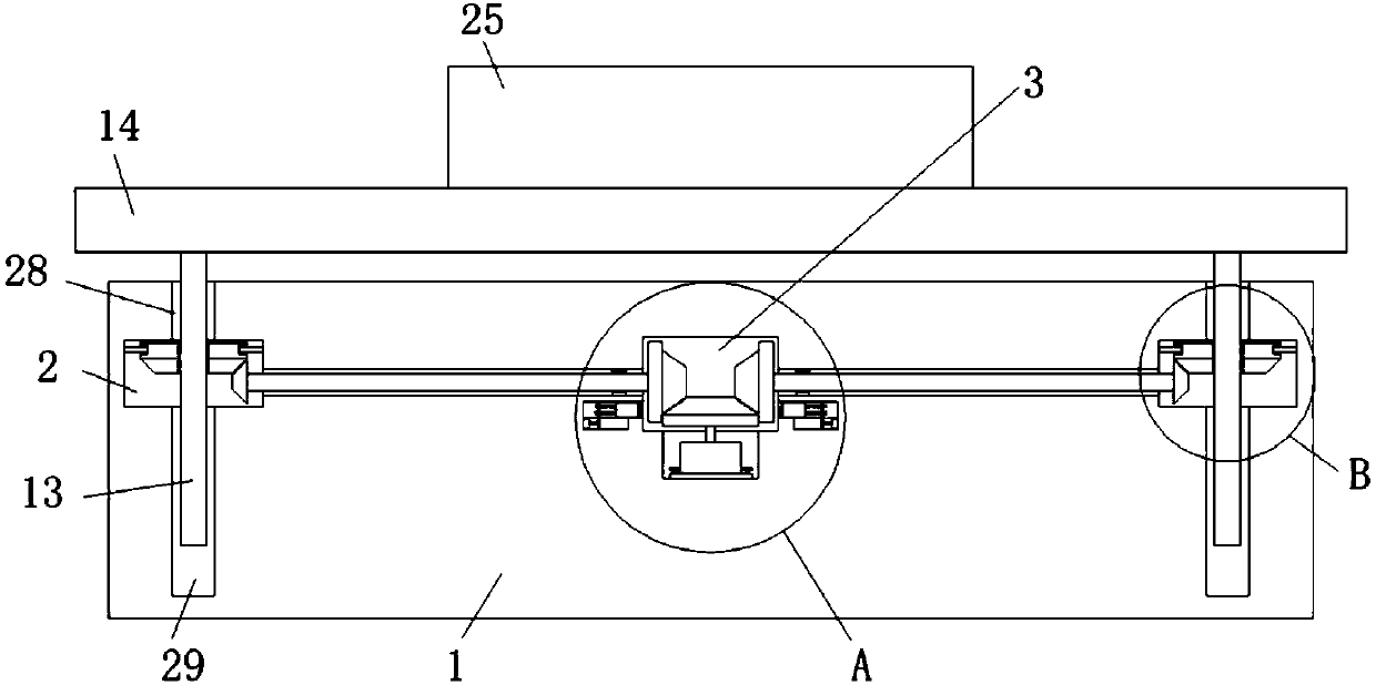
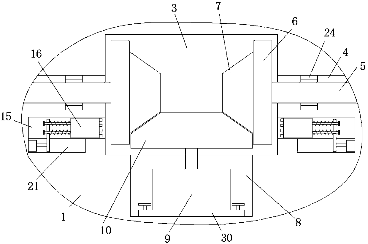
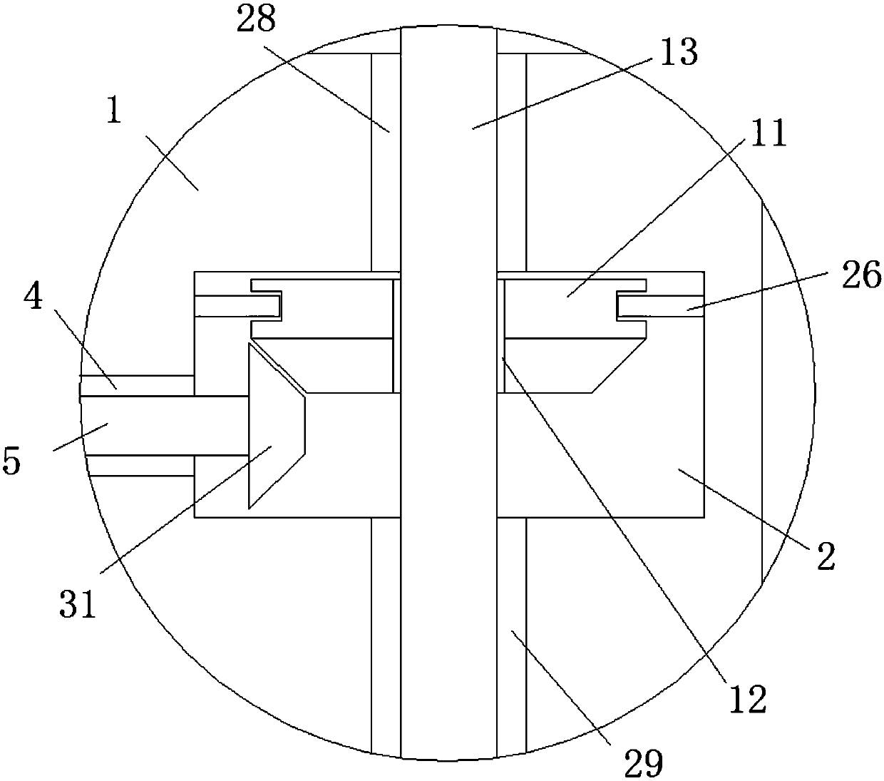
[0022] refer to Figure 1-5 In this embodiment, an elevating working platform for mold manufacturing is proposed, including a base 1 on which two symmetrically arranged rotating cavities 2 are provided, and the sides of the two rotating cavities 2 are provided with a In the mounting chamber 3 on the base 1, a rotating hole 4 is provided on both sides of the mounting chamber 3, and the rotating hole 4 communicates with the corresponding rotating chamber 2, and a driving rod 5 is installed in the rotating hole 4, two The ends of the drive rods 5 that are close to each other extend into the installation cavity 3 and are welded with a turntable 6, and the sides of the two turntables 6 that are close to each other are welded with a first bevel gear 7, and the bottom inner wall of the installation cavity 3 is provided with a mounting groove. 8. The drive motor 9 is installed in the installation groove 8, the output shaft of the drive motor 9 extends into the installation cavity 3 an...


PUM


Abstract

The invention discloses a lifting type working platform for mold manufacturing. The lifting type working platform comprises a base, two rotating cavities which are symmetrically arranged are formed inthe base, and a mounting cavity which is formed in the base is formed in the side, close to each other, of the two rotating cavities; rotating holes are formed in the inner walls of the two sides ofthe mounting cavity, and the rotating holes communicate with the corresponding rotating cavities; driving rods are rotationally installed in the rotating holes, and the ends, close to each other, of the two driving rods extend into the mounting cavities and are welded with rotating discs; and first umbrella-shaped gears are welded to the side, close to each other, of the two rotating discs, a mounting groove is formed in the inner wall of the bottom of the mounting cavity, and a driving motor is arranged in the mounting groove. The working platform is high in practicability, simple in structure and convenient to operate; a screw rod can be conveniently moved up and down so that the height of the platform can be adjusted; and rubber columns can be moved to be in contact with and tightly attached to the rotating discs so that the height of the platform can be fixed.

Description

technical field [0001] The invention relates to the technical field of mechanical equipment, in particular to an elevating working platform for mold manufacturing. Background technique [0002] my country is a big country in mold manufacturing. In the process of mold production and manufacturing, the mold will be placed on the platform for mold assembly. However, due to the different specifications of different molds, in order to facilitate the operator when assembling the mold, the mold will be placed on the platform. It is set as a liftable platform. The patent document CN104385238A provides a liftable work platform. This structure includes a workbench, a base, a lifting device and a transmission device. The lifting device is fixed in the base, and the workbench The built-in storage drawer is fixed on the top of the lifting device; the lifting device includes two reducers on both sides of the bottom of the workbench. The reducer is equipped with a screw that can be lifted ve...

Claims


Application Information

Patent Timeline
Patent Type & Authority Applications(China)
IPC IPC(8): B25H1/16B23P19/00
CPCB25H1/16B23P19/00
Inventor 不公告发明人
Owner RUGAO CITY XIANGQIANG MACHINERY EQUIP CO LTD
Why Eureka
Try Eureka