Switch cabinet with movable switch cabinet bracket device

A bracket device and switchgear technology, applied in cooling/ventilation of substation/switchgear, substation/switch layout details, substation/power distribution device shell, etc., can solve the problem of not being able to adjust the height according to needs, and save energy , Easy to use, easy to use effect

Inactive Publication Date: 2019-07-23
镇江茗驰电气有限公司
View PDF0 Cites 8 Cited by
  • Summary
  • Abstract
  • Description
  • Claims
  • Application Information

AI Technical Summary

Problems solved by technology

[0002] The switch cabinet is a kind of electrical equipment. The outside line of the switch cabinet first enters the main control switch in the cabinet, and then enters the sub-control switch. Each branch is set according to its needs, such as instruments, automatic control, motor magnetic switches, various AC contactors, etc. Some also have high-voltage room and low-voltage room switchgear, high-voltage busbars, such as power plants, etc., and some also have low-cycle load shedding to ensure the main equipment. At present, the switchgear on the market is usually a bolt for the internal supporting device. fixed, the height cannot be adjusted as required, therefore, it is necessary to invent a switchgear with a movable switchgear bracket device to solve the above problems

Method used


Image

  • Switch cabinet with movable switch cabinet bracket device
  • Switch cabinet with movable switch cabinet bracket device
  • Switch cabinet with movable switch cabinet bracket device

Examples


Embodiment Construction

[0020] The following will clearly and completely describe the technical solutions in the embodiments of the present invention with reference to the accompanying drawings in the embodiments of the present invention. Obviously, the described embodiments are only some, not all, embodiments of the present invention. Based on the embodiments of the present invention, all other embodiments obtained by persons of ordinary skill in the art without making creative efforts belong to the protection scope of the present invention.

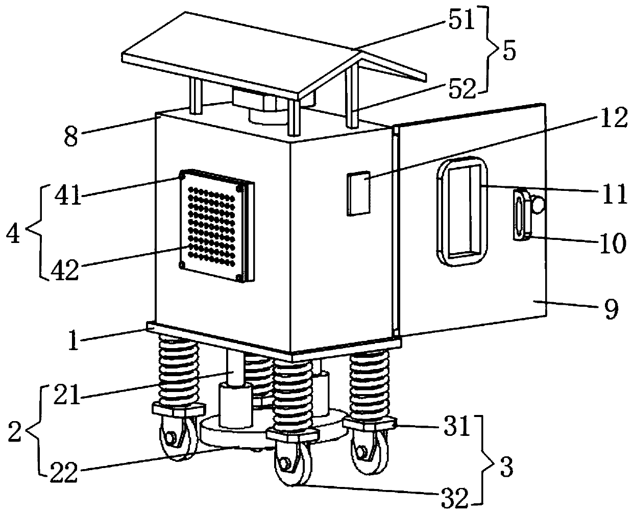
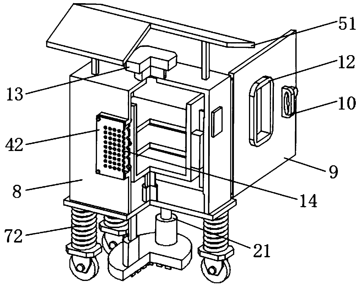
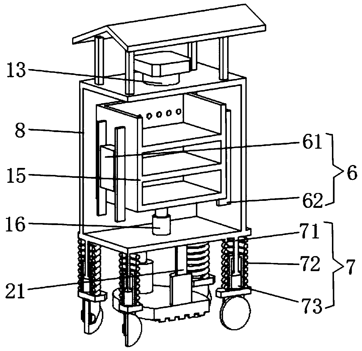
[0021] see Figure 1-3 , the present invention provides a technical solution: a switch cabinet with a movable switch cabinet bracket device, including a bottom plate 1, four shock absorbing mechanisms 7 are arranged at the bottom of the bottom plate 1, and the switch can be improved by the shock absorbing mechanism 7. The shock absorption of the cabinet when moving prevents the electrical components installed on the bracket 15 from being shaken. The bottom of ...


PUM


Abstract

The invention discloses a switch cabinet with a movable switch cabinet bracket device. The switch cabinet comprises a bottom plate, four damping mechanisms are arranged at the bottom of the bottom plate, a moving mechanism is arranged at the bottom of each damping mechanism, a fixing mechanism is arranged in the middle of the bottom plate, a switch cabinet body is arranged on the upper surface ofthe bottom plate, the side surface of the switch cabinet body is provided with a thermal dissipation groove, and a thermal dissipation plate is arranged in the thermal dissipation groove. According tothe switch cabinet with the movable switch cabinet bracket device, the switch cabinet is driven to move conveniently, physical strength of workers is saved, high flexibility, the switch cabinet is convenient to place stably, good in stability and convenient to use, the overall height of the switch cabinet can be adjusted conveniently, the damping performance of the switch cabinet during moving can be improved conveniently, the thermal dissipation performance of the switch cabinet can be improved conveniently, dust can be prevented from entering the switch cabinet body conveniently, a bracketcan be driven to move up and down conveniently, and using is convenient and fast.

Description

technical field [0001] The invention relates to the technical field of switch cabinets, in particular to a switch cabinet with a movable switch cabinet bracket device. Background technique [0002] The switch cabinet is a kind of electrical equipment. The outside line of the switch cabinet first enters the main control switch in the cabinet, and then enters the sub-control switch. Each branch is set according to its needs, such as instruments, automatic control, motor magnetic switches, various AC contactors, etc. Some also have high-voltage room and low-voltage room switchgear, high-voltage busbars, such as power plants, etc., and some also have low-cycle load shedding to ensure the main equipment. At present, the switchgear on the market is usually a bolt for the internal supporting device. It is fixed, and the height cannot be adjusted as required. Therefore, it is necessary to invent a switch cabinet with a movable switch cabinet bracket device to solve the above problem...

Claims


Application Information

Patent Timeline
Patent Type & Authority Applications(China)
IPC IPC(8): H02B1/56H02B1/54H02B1/50H02B1/28H02B1/30H02B1/36
CPCH02B1/28H02B1/30H02B1/36H02B1/50H02B1/54H02B1/565
Inventor 杨祥斌吴平阳陈震亚丁小雨
Owner 镇江茗驰电气有限公司
Why Eureka
Try Eureka