Detection mechanism and detection method for deviation of working position of mechanical arm

A technology of working position and detection mechanism, applied in the directions of manipulators, measuring devices, manufacturing tools, etc., can solve the problems of low efficiency, occupying production takt, affecting work efficiency, etc., and achieves high work efficiency, low cost, and automatic error-proof inspection. Effect

Active Publication Date: 2018-02-23
尊道(上海)自动化设备有限公司
View PDF12 Cites 4 Cited by
  • Summary
  • Abstract
  • Description
  • Claims
  • Application Information

AI Technical Summary

Problems solved by technology

[0004] 1. Using video camera equipment to automatically track, the software and hardware of the video camera analysis system are expensive, occupying the production cycle and affecting work efficiency;
[0005] 2. Equipped with hardware mandrel, manual calibration, low efficiency, human misjudgment may be possible, and automatic error-proof inspection cannot be realized;
[0006] 3. Configure measuring tools and manually calibrate, which is inefficient and cannot realize automatic error-proof inspection

Method used


Image

  • Detection mechanism and detection method for deviation of working position of mechanical arm
  • Detection mechanism and detection method for deviation of working position of mechanical arm
  • Detection mechanism and detection method for deviation of working position of mechanical arm

Examples


Embodiment Construction

[0029] The present invention will be described in detail below in conjunction with the accompanying drawings.

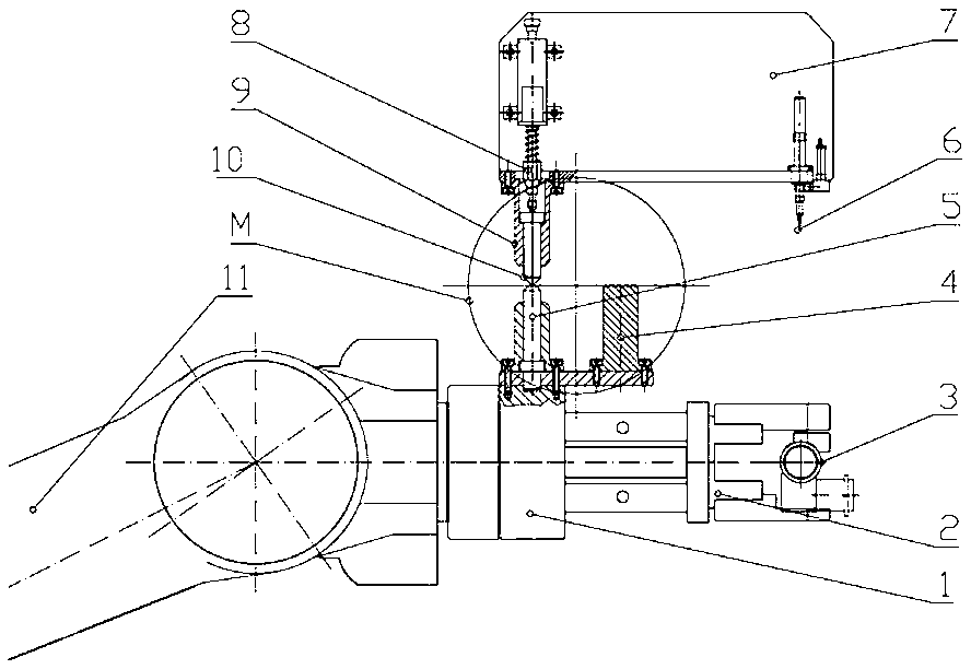
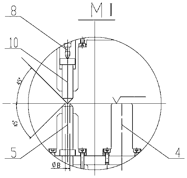
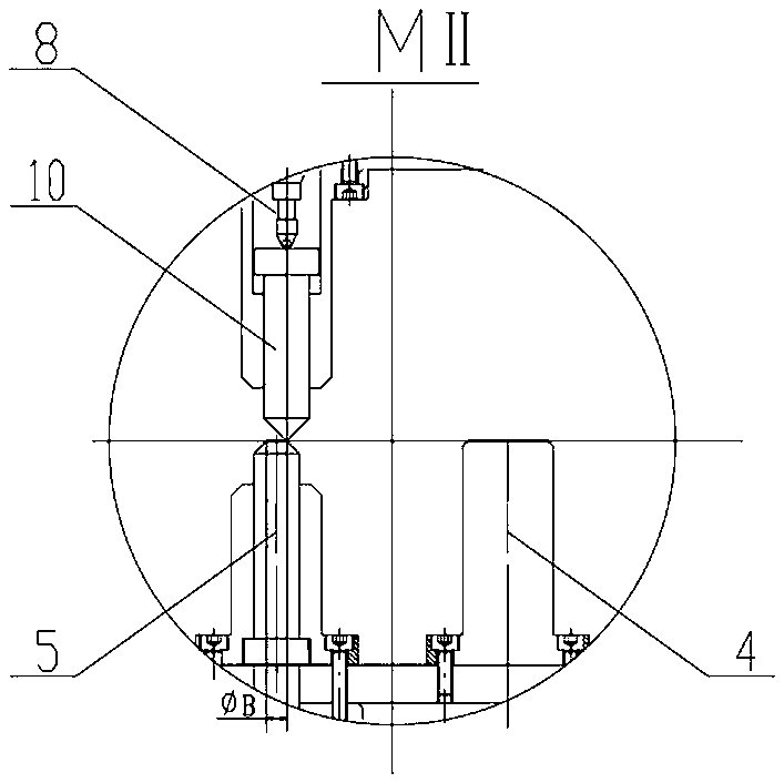
[0030] Such as figure 1 As shown, a detection mechanism for the deviation of the working position of the manipulator includes a mounting plate 7 arranged above the manipulator 11, a longitudinal guide sleeve 9 connected to the mounting plate 7, arranged in the guide sleeve 9 and protruding downward from the guide The tapered rod 10 of the sleeve 9, the displacement sensor 8 provided on the mounting plate 7 above the tapered rod 10 and the flat-end column 4 and the tapered-end flat-head column 5 installed side by side on the upper end of the manipulator 11 tooling 1, the detection end of the displacement sensor 8 is against At the top of the top cone rod 10, the guide sleeve 9 is provided with a limit edge, and the pointed cone rod 10 is provided with a limit end at the upper end of the limit edge. The top surface of the column 4 is on the same plane as the top surfa...


PUM


Abstract

The invention discloses a detection mechanism and detection method for deviation of the working position of a mechanical arm. The detection mechanism comprises an installing plate arranged above the mechanical arm, a guide sleeve connected to the longitudinal direction of the installing plate, a pointed cone rod arranged in the guide sleeve and extending out of the guide sleeve downwards, a displacement sensor, a flat end column and a cone point flat head column, wherein the displacement sensor is arranged on the portion, above the pointed cone rod, of the installing plate, and the flat end column and the cone point flat head column are installed at the upper end of the mechanical arm tool side by side. The detection end of the displacement sensor abuts against the top end of the pointed cone rod. A limiting edge is arranged in the guide sleeve. A limiting end head is arranged on the portion, located at the upper end of the limiting edge, of the pointed cone rod. The pointed cone rod is located above the flat end column and the cone point flat head column. The top face of the flat end column and the top face of the cone point flat head column are located on the same plane. According to the detection method, the displacement sensor detects the relative position of the pointed cone rod to the top face of the flat end column and the top face of the cone point flat head column to judge the deviation direction and the distance of the mechanical arm tool. The detection mechanism can prevent errors automatically and carry out check, and is lower in cost and higher in working efficiency.

Description

technical field [0001] The invention relates to the technical field of detection equipment and methods, in particular to a mechanism and method for detecting the deviation of the working position of a manipulator. Background technique [0002] In the prior art, work processes such as dispensing, oiling, soldering, assembly, and handling are often completed by joint robots or XYZ three-axis coordinate robots. The joint robot or XYZ three-axis coordinate robot often causes the working position of the manipulator to deviate due to the replacement of the tooling on the manipulator, the replacement of the manipulator or the working head, and the maintenance of the manipulator, which causes the robot to interfere when it is working. At this time, it is necessary to quickly and automatically detect the origin of the working position of the manipulator to determine whether the origin of the working position deviates from the allowable range. [0003] In the prior art, there are aut...

Claims


Application Information

Patent Timeline
IPC IPC(8): B25J19/00G01B21/00
CPCG01B21/00B25J19/0095
Inventor 周煜人周益范陈涌虎
Owner 尊道(上海)自动化设备有限公司
Why Eureka
Try Eureka