
Automobile front collision energy absorption protection structure

A frontal collision and protection structure technology, applied in bumpers, vehicle parts, vehicle safety arrangements, etc., can solve problems such as insufficient energy absorption, and achieve a stable and efficient energy absorption process, reasonable structure, and strong safety protection capabilities. Effect

Active Publication Date: 2018-02-23
ZHEJIANG LEAPMOTOR TECH CO LTD
View PDF5 Cites 9 Cited by
  • Summary
  • Abstract
  • Description
  • Claims
  • Application Information

AI Technical Summary

Problems solved by technology

However, the deformation form of the energy-absorbing box is plastic deformation, there are many uncertain factors, and it is impossible to fully absorb energy.

Method used


Image

  • Automobile front collision energy absorption protection structure
  • Automobile front collision energy absorption protection structure
  • Automobile front collision energy absorption protection structure

Examples


Embodiment 1

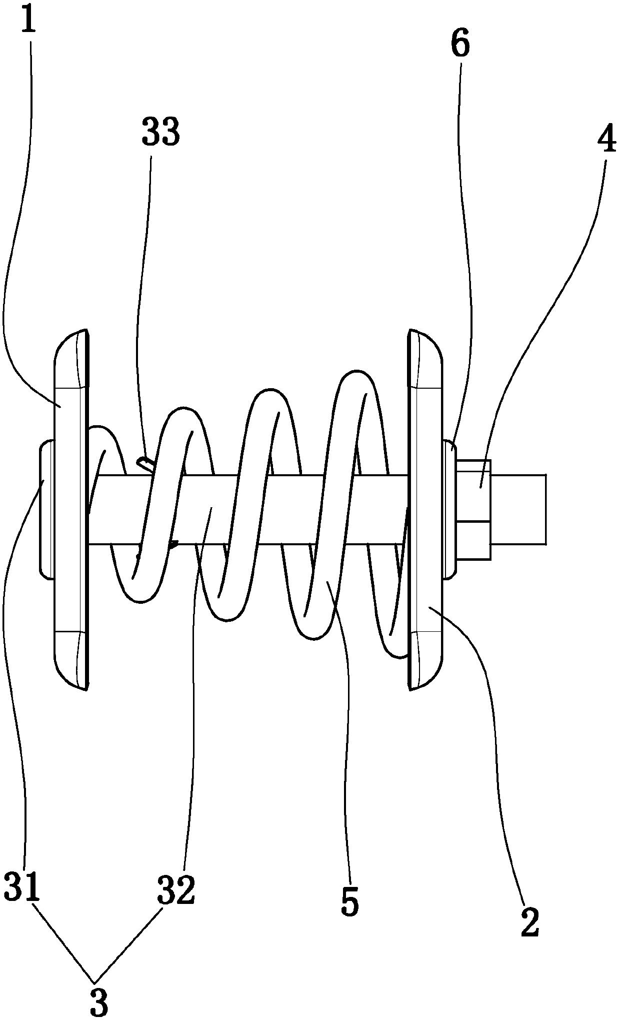
[0023] Embodiment 1: as figure 1 In the shown embodiment, a kind of energy-absorbing protection structure of automobile frontal collision, comprises

[0024] Energy-absorbing front seat 1, energy-absorbing rear seat 2, fixing bolt 3, fixing nut 4 and energy-absorbing spring 5, the fixing bolt includes a bolt head 31 welded with the front anti-collision beam of the automobile and a stud welded with the front longitudinal beam of the automobile 32;

[0025] The stud passes through the energy-absorbing front seat and the energy-absorbing rear seat, the energy-absorbing spring is sleeved outside the stud, and the energy-absorbing spring is located between the energy-absorbing front seat and the energy-absorbing rear seat;

[0026] The fixing nut is threadedly connected with the stud, and on the axial direction of the stud: the bolt head, the energy-absorbing front seat, the energy-absorbing spring, the energy-absorbing back seat and the fixing nut are arranged in sequence.

[00...

Embodiment 2

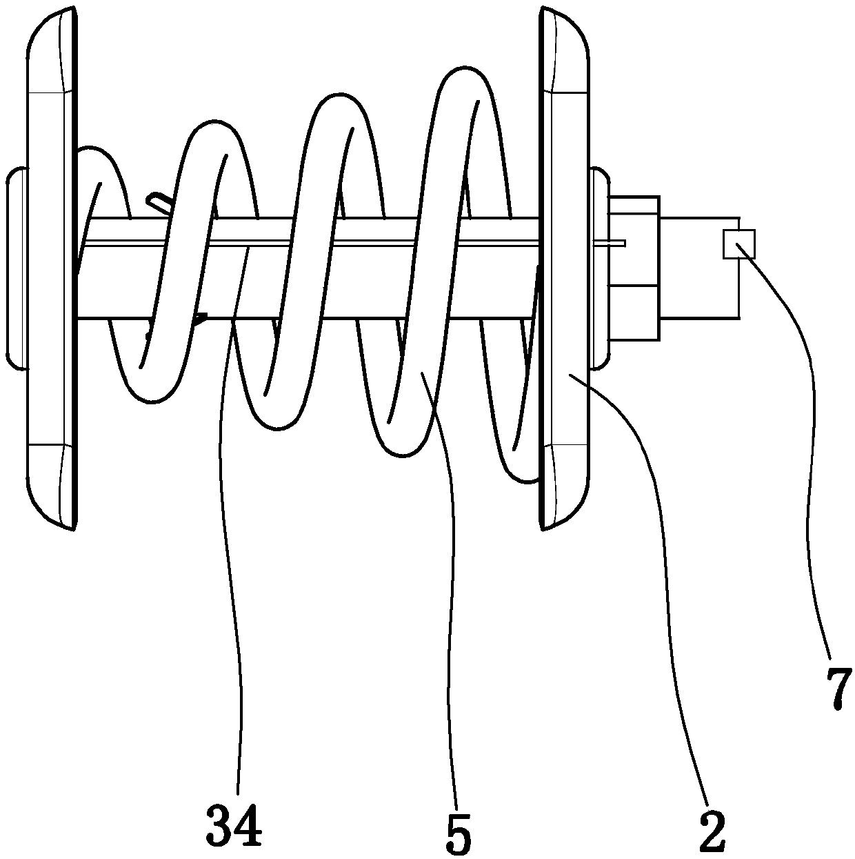
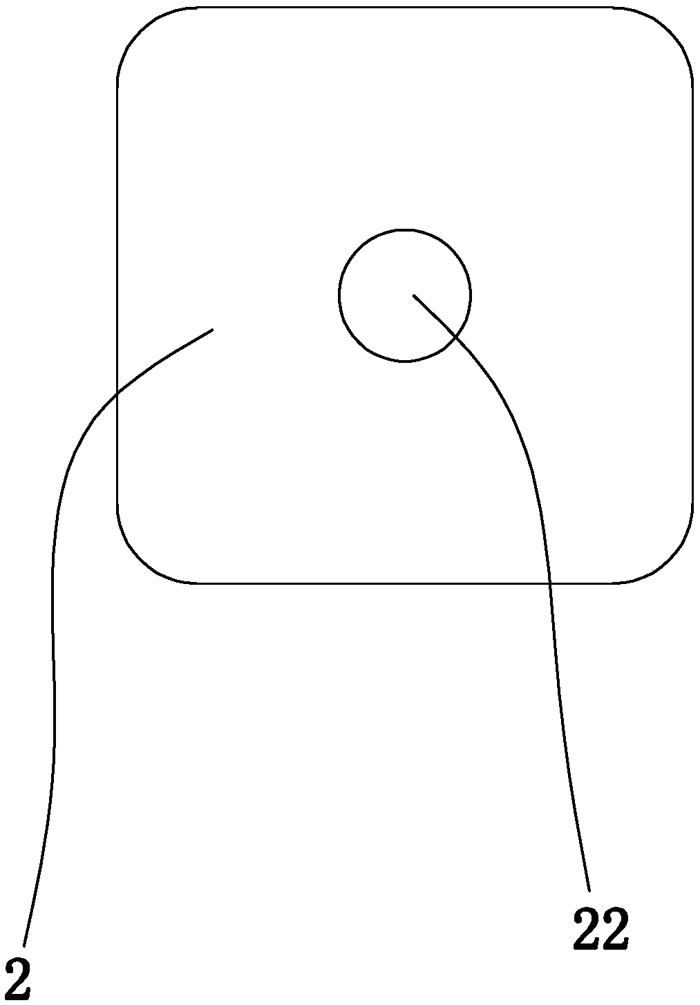
[0032] Embodiment 2: the basic structure and implementation mode of this embodiment are the same as embodiment 1, and its difference is, as Figure 2 to Figure 4 As shown in , the energy-absorbing rear seat is provided with a number of barb extrusion holes 21 corresponding to the elastic barbs one by one, the energy-absorbing front seat is provided with a front seat middle hole 11, and the energy-absorbing rear seat is provided with a middle hole 11 of the rear seat. Hole 22, stud passes the middle hole of the front seat, and stud passes the middle hole of the rear seat, and the barb squeezes through the hole and communicates with the middle hole of the rear seat. The existence of extrusion holes can reduce the difficulty of elastic barbs passing through the energy-absorbing rear seat and improve the smoothness of work.

[0033] The energy-absorbing front seat is provided with a guide rod 34, and the energy-absorbing rear seat is provided with a guide hole slidingly matched wi...


PUM


Abstract

The invention discloses an automobile front collision energy absorption protection structure. The structure comprises an energy absorption front base, an energy absorption rear base, a fixing bolt, afixing nut and an energy absorption spring, wherein the fixing bolt comprises a bolt head and a column, the bolt head is welded to an automobile front anti-collision beam, and the bolt column is welded to an automobile front longitudinal beam; the bolt column penetrates through the energy absorption front base and the energy absorption rear base and is sleeved with the energy absorption spring, and the energy absorption spring is located between the energy absorption front base and the energy absorption rear base; the fixing nut is in threaded connection with the bolt column in the axial direction of the bolt column; the bolt head, the energy absorption front base, the energy absorption spring, the energy absorption rear base and the fixing nut are sequentially distributed. The protectionstructure has the advantages that the structure is reasonable, when an automobile collides from the front, energy can be effectively absorbed, the energy absorption process is stable and efficient, the energy absorption effect is good, and the safety protection capacity is high; the two-stage protection effect is achieved, avoiding space can be automatically provided, and personal protection of adriver is facilitated.

Description

technical field [0001] The invention belongs to the technical field of automobile protection devices, and in particular relates to an energy-absorbing protective structure for automobile frontal collision. Background technique [0002] Generally, an energy-absorbing box is added to the connection between the front anti-collision beam and the front longitudinal beam of a car, which is used to initially absorb the collision energy of the vehicle and reduce the damage to the occupants. The energy-absorbing box is generally designed with a closed steel plate, and the energy is absorbed through the deformation of the energy-absorbing box. However, the deformation form of the energy-absorbing box is plastic deformation, there are many uncertain factors, and it is impossible to fully absorb energy. Contents of the invention [0003] The invention aims to overcome the deficiencies in the prior art, and provides a vehicle with a reasonable structure, which can effectively absorb e...

Claims


Application Information

Patent Timeline
IPC IPC(8): B60R19/02
CPCB60R19/023B60R2019/026
Inventor 田占国李卓富
Owner ZHEJIANG LEAPMOTOR TECH CO LTD
Learn More