Steering System

A control device, rack technology, applied in steering control, steering mechanism, mechanical steering gear, etc., can solve problems such as differences

Inactive Publication Date: 2018-02-23
JTEKT CORP
View PDF8 Cites 1 Cited by
  • Summary
  • Abstract
  • Description
  • Claims
  • Application Information

AI Technical Summary

Problems solved by technology

As a result, since the position of the steering wheel (rotation angle from the initial position) is different when starting to operate the steering wheel, the force (initial operating force) required to start operating the steering wheel is different.

Method used


Image

  • Steering System
  • Steering System
  • Steering System

Examples


Embodiment Construction

[0025] The above and other features and advantages of the present invention will become more apparent from the following detailed description of examples of embodiments of the present invention with reference to the accompanying drawings, wherein like reference numerals denote like elements.

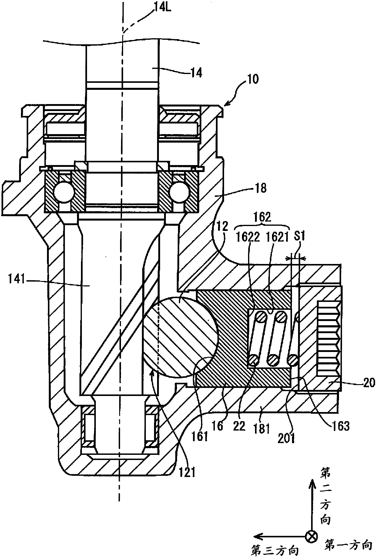
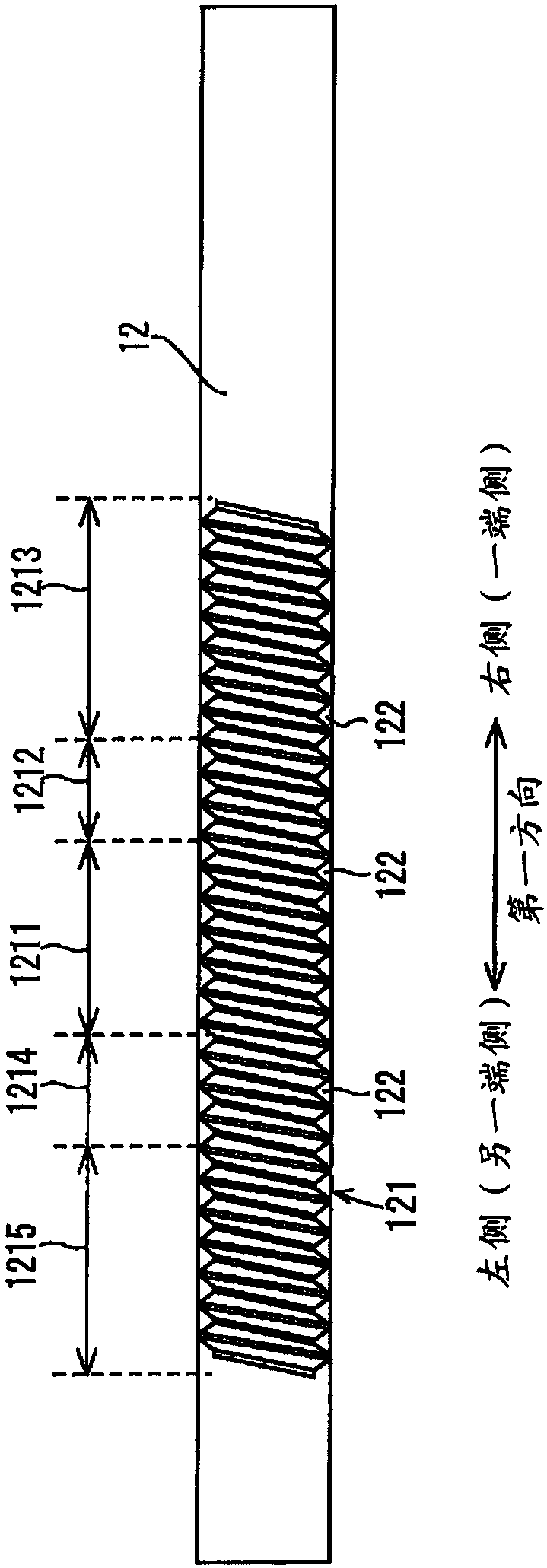
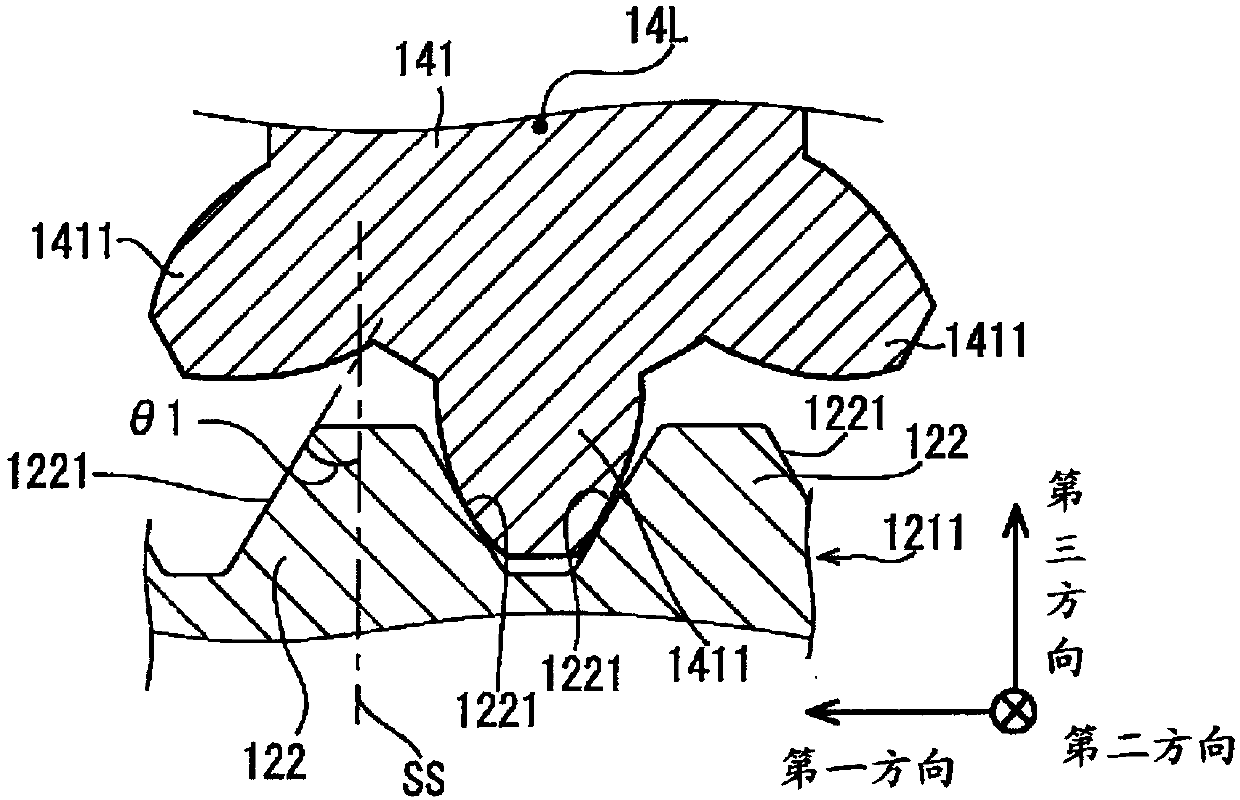
[0026] A steering device according to an embodiment of the present invention includes a rack shaft, a pinion shaft, a rack guide, a housing, a guide plug, and an urging member. The rack shaft extends along the first direction. A rack is formed on the rack shaft. The rack has a plurality of rack teeth. The plurality of rack teeth are arranged along the first direction. The pinion shaft extends in the second direction. The second direction is a direction intersecting the first direction. The pinion shaft has a pinion. The pinion meshes with the rack. The rack guide is in contact with the rack shaft in the third direction. The third direction is a direction perpendicular to the first...


PUM


Abstract

The present invention relates to a steering system. A ratio of the distance by which a rack shaft moves in a first direction relative to the angle by which a pinion shaft rotates in a circumferentialdirection is defined as a stroke ratio. The stroke ratio is larger when the pinion meshes with one of a third rack and a fifth rack than when the pinion meshes with a first rack. The stroke ratio changes while the pinion moves on one of a second rack and a fourth rack. A clearance defined between a rack guide and a guide plug is smaller when the pinion meshes with one of the third rack and the fifth rack than when the pinion meshes with the first rack. The clearance defined between the rack guide and the guide plug changes while the pinion moves on one of the second rack and the fourth rack.

Description

[0001] This application claims the priority of Japanese Patent Application No. 2016-158064 filed on August 10, 2016 and Japanese Patent Application No. 2017-001003 filed on January 6, 2017, and cites the specification and drawings here and the entire contents of the abstract. technical field [0002] This invention relates to steering devices, and more particularly to rack and pinion steering devices. Background technique [0003] In order to change the direction of travel of the vehicle, a steering device is installed on the car. The steering device is, for example, a rack and pinion type steering device. [0004] Rack and pinion steering has a pinion shaft and a rack shaft. The pinion shaft has a pinion. The pinion meshes with a rack provided on the rack shaft. The rack has a plurality of rack teeth arranged in the axial direction of the rack shaft. The pinion shaft is connected to the steering shaft. The steering shaft is connected with a steering wheel. Steering w...

Claims


Application Information

Patent Timeline
Patent Type & Authority Applications(China)
IPC IPC(8): B62D3/12
CPCB62D3/12F16H55/283B62D5/0463B62D6/10B62D5/04B62D6/00B62D1/166
Inventor 三井邦晃
Owner JTEKT CORP
Why Eureka
Try Eureka