Variable-angle flip bucket and shutter type stilling pool tail bucket combined energy dissipation structure and using method thereof

A louver-type and stilling pool technology, which is applied in water conservancy projects, marine engineering, coastline protection, etc., can solve problems such as cavitation and erosion on the dam surface, and achieve improved cavitation resistance, energy dissipation efficiency, and energy dissipation rate Effect

Active Publication Date: 2018-02-23
KUNMING UNIV OF SCI & TECH
View PDF3 Cites 0 Cited by
  • Summary
  • Abstract
  • Description
  • Claims
  • Application Information

AI Technical Summary

Problems solved by technology

[0007] Aiming at the deficiencies of air entrainment and dam surface cavitation and erosion in the current design of hydraulic structure discharge and energy dissipation, the present invention provides a combined energy dissipation structure and its Instructions

Method used


Image

  • Variable-angle flip bucket and shutter type stilling pool tail bucket combined energy dissipation structure and using method thereof
  • Variable-angle flip bucket and shutter type stilling pool tail bucket combined energy dissipation structure and using method thereof
  • Variable-angle flip bucket and shutter type stilling pool tail bucket combined energy dissipation structure and using method thereof

Examples


Embodiment 1

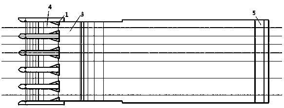
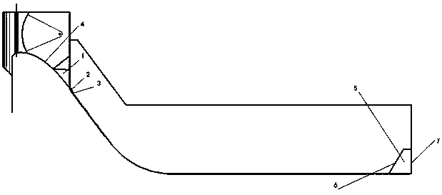
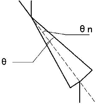
[0033] In the variable-angle ridge part of this example, the end of the wide-tailed pier 1 is connected to the head of the variable-angle ridge 2, and the tail of the variable-angle ridge 2 is connected to the first step of the stepped overflow dam 3, and the water flows through the end of the wide-tailed pier 1. The flow direction changes angle to pick up the ridge 2, and then flows to the stepped overflow dam 3 through the pick up ridge, when the single-width flow rate at the top of the weir is 235m 3 / s·m—270 m 3 When within the / s m range, by adjusting the angle of the hurdle θ 1 12° to change the shape of the water flow through the weir, so that the water flow ejected from the end of the wide-tailed pier 1 can be adjusted by adjusting the angle of the ridge 2 θ 1 To make the injected water fully contact with the air, and create aeration conditions at the bottom of the water tongue, increase the aeration cavity and aeration concentration, and provide the energy dissipat...

Embodiment 2

[0037] In the variable-angle ridge part of this example, the end of the wide-tailed pier 1 is connected to the head of the variable-angle ridge 2, and the tail of the variable-angle ridge 2 is connected to the first step of the stepped overflow dam 3, and the water flows through the end of the wide-tailed pier 1. The flow direction is changed to pick up the ridge 2, and then flow to the stepped overflow dam 3 through the pick up dam. When the single width flow at the weir top is 190m 3 / s·m—235 m 3 / s m range, by adjusting the angle of the hurdle θ 2 8° to change the shape of the water flow through the weir, so that the water flow ejected from the end of the wide-tailed pier 1 can be adjusted by adjusting the angle of the ridge 2 θ 2 To make the injected water fully contact with the air, and create aeration conditions at the bottom of the water tongue, increase the aeration cavity and aeration concentration, and provide the energy dissipation rate of the stepped overflow da...

Embodiment 3

[0041] In the variable-angle ridge part of this example, the end of the wide-tailed pier 1 is connected to the head of the variable-angle ridge 2, and the tail of the variable-angle ridge 2 is connected to the first step of the stepped overflow dam 3, and the water flows through the end of the wide-tailed pier 1. The flow direction is changed to pick the ridge 2, and then flow to the stepped overflow dam 3 through the pick ridge, when the single-width flow of the weir crest does not exceed 190m 3 / s·m, by adjusting the angle of the hurdle θ 3 3° to change the shape of the water flow over the weir, so that the water flow ejected from the end of the wide-tailed pier 1 can be adjusted by adjusting the angle of the ridge 2 θ 3 To make the injected water fully contact with the air, and create aeration conditions at the bottom of the water tongue, increase the aeration cavity and aeration concentration, and provide the energy dissipation rate of the stepped overflow dam;

[0042]...


PUM


Abstract

The invention relates to a variable-angle flip bucket and shutter type stilling pool tail bucket combined energy dissipation structure and a using method thereof. According to the variable-angle flipbucket and shutter type stilling pool tail bucket combined energy dissipation structure, the tails of wide tail piers are connected with the head of a flip bucket, the tail of the flip bucket is connected with the first step of a stepped overflow dam, the upstream side and the downstream side of a stilling pool tail bucket are each of a shutter type, and the flip bucket is a variable-angle flip bucket. Through the optimization in the aspects of the angle of the flip bucket and the opening degrees of blades on the upstream side and the downstream side of the shutter type stilling pool tail bucket, firstly, energy dissipation for all stages of flow is greatly improved, and although the back negative pressure of steps is slightly high, the back negative pressure is still within the standard range; secondly, the concentration of entrained air of the bottom step can be increased, and the first several steps are protected through the flip bucket on the front portion, so that the cavitation erosion resistance is obviously improved, and the energy dissipation effect is remarkab; thirdly, the water flow state in a stilling pool is changed, and the pulse load of a bottom plate and the energyefficiency of the stilling pool are greatly improved; and finally, the phenomenon of atomization generated in the drainage process is improved, and water flow discharged out of the pool is made smoother.

Description

technical field [0001] The invention relates to a combined energy-dissipating structure with variable-angle sills and louver-type stilling pool tail sills and a use method thereof, belonging to the field of flood discharge and energy dissipation of hydraulic structures in water conservancy and hydropower projects. Background technique [0002] In the design of dam engineering, flood discharge and energy dissipation are the two major tasks undertaken by the discharge structure, that is, to safely discharge excess flood water while strictly controlling the erosion of the dam body and downstream foundation pit by the discharge flow to prevent damage to the dam body and instability of the dam foundation . Especially for flood discharge projects with high water head and large flow, there are problems such as large flow velocity and pulsating pressure at the bottom of the bottom plate, high difficulty in anti-shock protection, large size of stilling basin required, and high cost. ...

Claims


Application Information

Patent Timeline
Patent Type & Authority Applications(China)
IPC IPC(8): E02B8/06
CPCE02B8/06
Inventor 杨具瑞汤建青郭莹莹
Owner KUNMING UNIV OF SCI & TECH
Why Eureka
Try Eureka