Pretreatment system of SCR (selective catalytic reduction) catalyst device

A technology of SCR catalyst and front plate, which is applied in the field of exhaust gas treatment devices, can solve the problems of lack of rectification design, poor effect of SCR reduction reaction, etc., and achieve the effect of saving assembly space, improving effect and improving treatment efficiency

Pending Publication Date: 2019-02-22
DONGFENG COMML VEHICLE CO LTD
View PDF8 Cites 0 Cited by
  • Summary
  • Abstract
  • Description
  • Claims
  • Application Information

AI Technical Summary

Problems solved by technology

[0007] The purpose of the present invention is to overcome the defects and problems existing in the prior art that additional mixers are required, lack of rectification design, and poor SCR reduction reaction effect, and provide a method that does not require additional mixers, is equipped with rectification design, and SCR reduction reaction Pre-treatment system of SCR catalyst device with good effect

Method used


Image

  • Pretreatment system of SCR (selective catalytic reduction) catalyst device
  • Pretreatment system of SCR (selective catalytic reduction) catalyst device
  • Pretreatment system of SCR (selective catalytic reduction) catalyst device

Examples


Embodiment 1

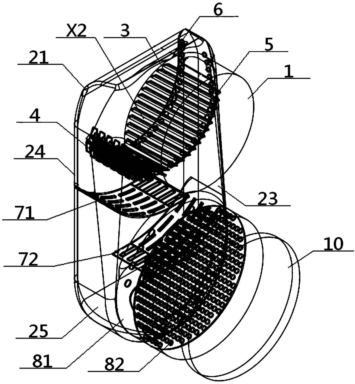
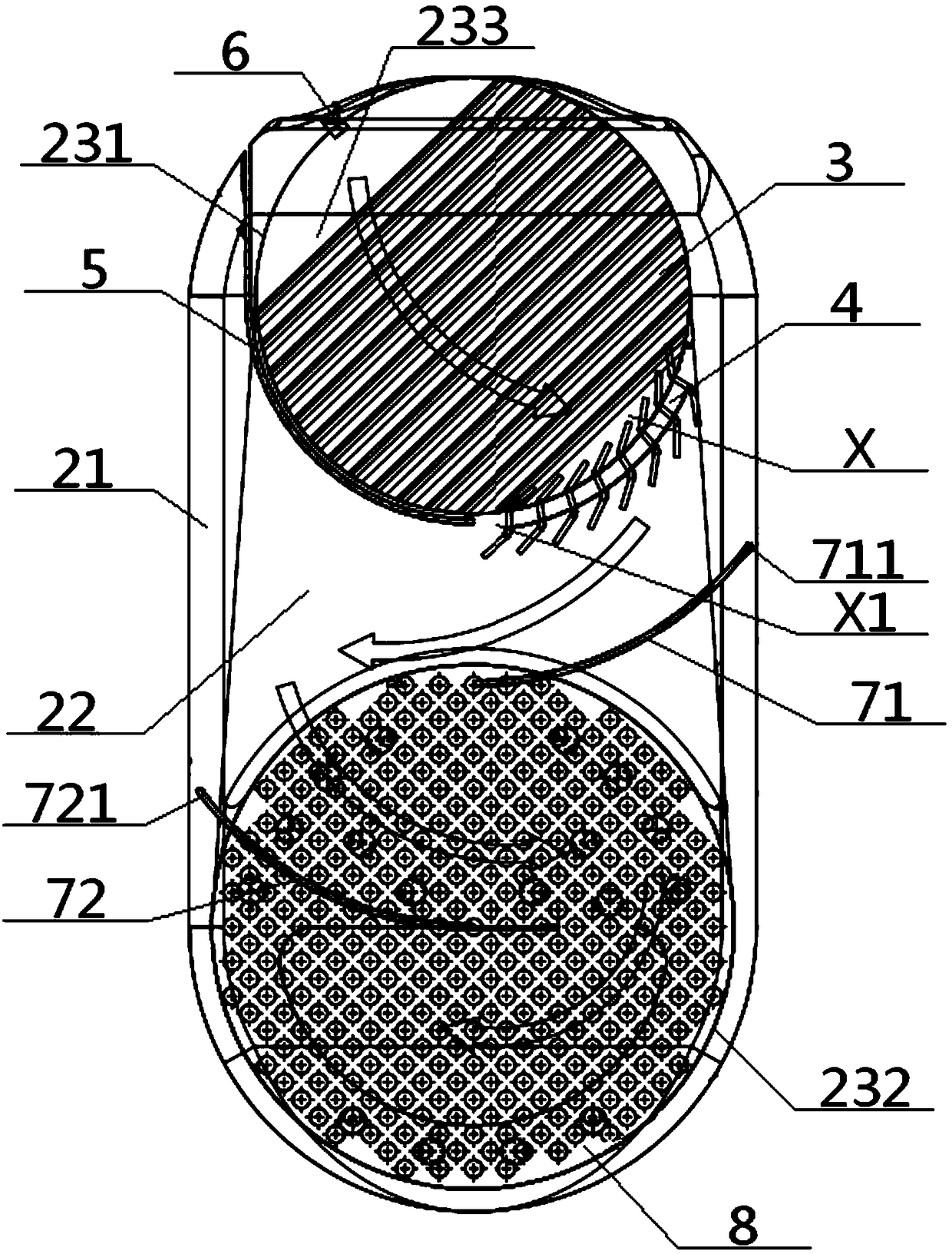
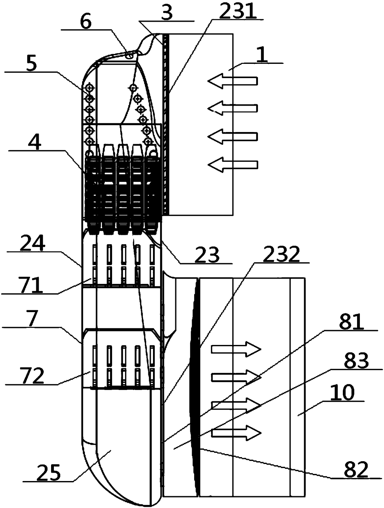
[0054] see Figure 1 to Figure 9 , a pretreatment system of an SCR catalyst device, comprising a DPF input end 1, an SCR output end 10 and a transition part 2, one end of the transition part 2 communicates with the DPF particle trapping device through the DPF input end 1, and the transition part 2 The other end communicates with the SCR catalyst device through the SCR output port 10; the transition part 2 includes a transition housing 21 and a transition cavity 22 provided inside, and the transition housing 21 includes a transition front plate 23, a transition rear plate 24 and a transition between two There is a ring-shaped transitional side wall 25 between them, the top of the transitional front plate 23 is provided with a front panel inlet 231 communicating with the DPF input end 1, and the bottom of the transitional front panel 23 is provided with a front panel inlet 231 communicated with the SCR output end 10. The plate outlet 232, and the DPF input end 1, the transition ...

Embodiment 2

[0056] Basic content is the same as embodiment 1, the difference is:

[0057] The vertical rectification unit 7 includes an arc-shaped upper orifice plate 71 and an arc-shaped lower orifice plate 72 arranged up and down. The arc-shaped upper orifice plate 71 includes an arc-shaped upper connection end 711, an arc-shaped middle hole portion 712, and an arc-shaped upper orifice plate 71 connected in sequence. The upper hanging end 713, the upper arc hole portion 712 is provided with a plurality of arc air vents 714, and the arc-shaped lower orifice plate 72 includes the arc lower connecting end 721, the arc lower middle hole portion 722 and the arc lower hole. The overhanging end 723 and the under-arc middle hole 722 are provided with a plurality of under-arc ventilation holes 724; the above-arc connecting end 711 is connected to the transition side wall 25, and the above-arc middle hole 712 and the over-arc hanging end 713 are all located at Right below the ammonia gas generati...

Embodiment 3

[0059] Basic content is the same as embodiment 1, the difference is:

[0060] The horizontal rectification unit 8 includes a rectification inner orifice plate 81 and a rectification outer orifice plate 82 arranged coaxially. Inside the SCR output end 10, the part of the SCR output end 10 sandwiched between the rectification inner orifice plate 81 and the rectification outer orifice plate 82 is a rectification orifice cavity 83, and the rectification inner orifice plate 81 is provided with a plurality of rectification inner orifice plates. Holes 84, the rectification outer orifice plate 82 is provided with a plurality of rectification outer holes 85.


PUM


Abstract

The invention provides a pretreatment system of an SCR (selective catalytic reduction) catalyst device. A transition part internally arranged between a DPF (diesel particulate filter) input end and anSCR output end comprises a transition casing and a transition cavity arranged in the transition casing, the transition casing comprises a front transition plate, a rear transition plate and a ring-shaped transition side wall clamped between the front transition plate and the rear transition plate, a front plate inlet and a front plate outlet are formed in the top and bottom of the front transition plate respectively, an ammonia gas generation unit is arranged in the position, close to the front plate inlet, in the transition cavity, and a vertical rectifying unit is arranged in the position,located below the ammonia gas generation unit, in the transition cavity; a horizontal rectifying unit is arranged in the SCR output end, and a urea jet hole communicated with the ammonia gas generation unit is formed in the top of the transition side wall. The design not only is beneficial to ammonia gas generation, but also facilitates increase of uniformity of ammonia gas concentration and flowrate, so that the SCR reaction effect is improved.

Description

technical field [0001] The invention relates to an exhaust gas treatment device, in particular to a pre-treatment system of an SCR catalyst device, which is specifically suitable for avoiding an additional mixer, and is equipped with a rectification design, which can improve the effect of the SCR reduction reaction. Background technique [0002] Selective Catalytic Reduction technology (Selective Catalytic Reduction, SCR) refers to the use of ammonia, ammonia water, urea or hydrocarbons as reducing agents to reduce NOx to N2, so as to achieve the treatment of tail gas to meet the emission standards. In the prior art, it is necessary to firstly process the exhaust gas of the engine to generate NOx mainly composed of ammonia, and then send it to the SCR catalyst device for SCR reduction reaction. [0003] The application publication number is CN108194176A, and the application publication date is June 22, 2018. The invention patent application discloses a U-shaped mixer device ...

Claims


Application Information

Patent Timeline
Patent Type & Authority Applications(China)
IPC IPC(8): B01D53/90B01D53/56B01D53/94
CPCB01D53/8631B01D53/90B01D53/9431B01D2251/2062
Inventor 王启琛冯坦
Owner DONGFENG COMML VEHICLE CO LTD
Why Eureka
Try Eureka