Power cable erecting device

A technology for power cables and equipment, applied in the field of cable erection, which can solve problems such as inconsistent soil density, uneven settlement of soil foundation, and tipping of erecting poles, so as to speed up the progress, improve the efficiency of compaction work, and reduce the quality of compaction. cost effect

Inactive Publication Date: 2018-02-23
杜勉
View PDF0 Cites 1 Cited by
  • Summary
  • Abstract
  • Description
  • Claims
  • Application Information

AI Technical Summary

Problems solved by technology

The traditional method is to use a shovel to tap the ground after backfilling the soil layer. This method is time-consuming and laborious, and the densit

Method used


Image

  • Power cable erecting device
  • Power cable erecting device
  • Power cable erecting device

Examples


Example Embodiment

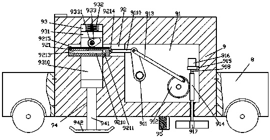
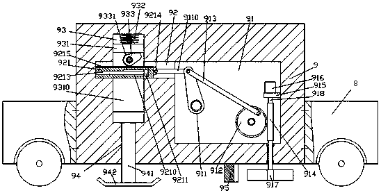
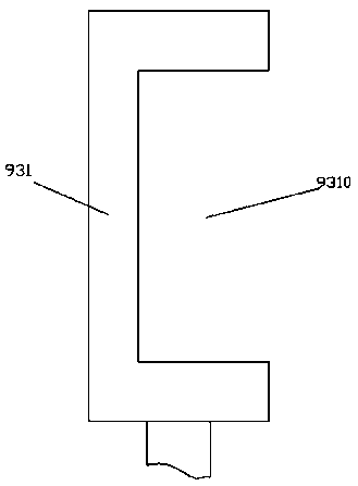
[0015] Such as Figure 1-Figure 4 As shown, a power cable erection device of the present invention includes a base 8 and a tapping machine 9 fixed in the base 8. The tapping machine 9 is provided with a chamber 91, the chamber 91 left The inner wall of the side top is connected with a guide groove 92 extending to the left. The left side of the guide groove 92 is provided with a guide cavity 93 extending up and down. The inner bottom wall of the guide cavity 93 communicates with A guide hole 94 extending downward and passing through the bottom surface of the base body 8 is slidingly connected with a take-off and landing sliding block 931 in the guide cavity 93. A recessed groove 9310 is provided in the front side of the take-off and landing sliding block 931. The inlet groove 9310 is communicated with the guide groove 92, a guide block 921 is slidably connected in the guide groove 92, the guide block 921 is connected with the recessed groove 9310 in clearance fit, and the top su...


PUM


Abstract

The invention discloses a device for power cable erection, which comprises a base body and a knocker fixed in the base body. A chamber is arranged in the knocker, and a guide extending to the left is arranged in the inner wall of the left top of the chamber. There is a guide cavity extending up and down in the extension section on the left side of the guide groove, and the bottom wall of the guide cavity is connected with a guide hole extending downward and penetrating the bottom surface of the base body. The sliding in the guide cavity is connected with a lifting slide block. There is a recessed groove in the front side of the take-off and landing sliding block, and the recessed groove is connected with the guide groove, and the guide block is slidingly connected in the guide groove, and the guide block is connected with the recessed groove. The top surface of the guide block is provided with a tooth shape There is a convex wheel in the recessed groove above the toothed bar; the invention improves the working efficiency and quality of knocking, speeds up the progress of cable erection, and reduces the cost of cable erection.

Description

technical field [0001] The invention relates to the technical field of cable erection, in particular to equipment for erecting electric cables. Background technique [0002] In order to improve the urban and rural power distribution, it is necessary to increase the laying of the power line network in a reasonable and orderly manner. Before erecting the cables, it is necessary to dig a hole in the bottom surface to fix the cable rack. The stability of the cable rack is directly related to the safety and quality of the line erection. . The traditional way is to use a shovel to tap the ground after backfilling the soil layer. This method is time-consuming and laborious, and the density of the soil layer is inconsistent. In case of heavy rain, the soil foundation is prone to uneven settlement, which can easily lead to the pole toppling. Contents of the invention [0003] The technical problem to be solved by the present invention is to provide a device for erecting power cabl...

Claims


Application Information

Patent Timeline
IPC IPC(8): E04H12/34E02D3/046E02F5/22
CPCE04H12/347E02D3/046E02F5/226
Inventor 杜勉
Owner 杜勉
Why Eureka
Try Eureka