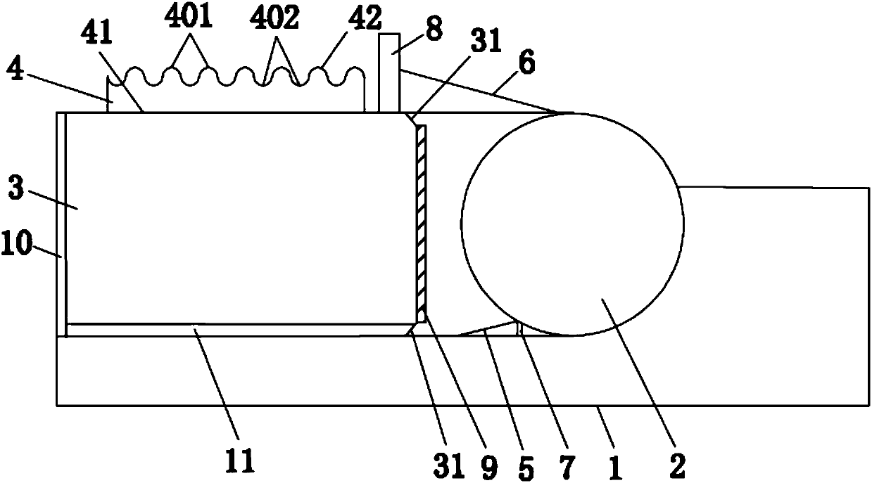
Backlight module capable of reducing required usage quantity of LEDs
A technology of backlight module and quantity, which is applied in the field of backlight module, can solve the problems of increasing production cost, fully utilizing the backlight source, and low light utilization rate of the backlight source, and achieves the effect of simple structure and low production cost
- Summary
- Abstract
- Description
- Claims
- Application Information
AI Technical Summary
Problems solved by technology
Method used
Image
Examples
Embodiment 1
[0038] A backlight module that can reduce the number of LEDs required in this embodiment, such as figure 1 As shown, it includes a back frame 1, a backlight 2 arranged in the back frame 1 and composed of a plurality of light emitting sources, a light guide plate 3 arranged on one side of the backlight 2, and a diffusion plate 4 arranged on the light guide plate 3 The side of the light guide plate 3 incident on the backlight 2 is provided with a light effect enhancing medium 9, the side of the light guide plate 3 opposite to the backlight 2 is provided with a first reflective film 10, and the side of the light guide plate 3 opposite to the diffusion plate 4 is provided with a second Two reflective films 11, the reflective surface of the first reflective film 10 faces the backlight 2, the reflective surface of the second reflective film 11 faces the diffuser plate 4; both ends of the side of the light guide plate 3 facing the backlight 2 are provided with chamfers 31; the backli...
Embodiment 2
[0049] Embodiment 2 of the backlight module of the present invention that can reduce the number of LEDs required is different from Embodiment 1 in that, in this embodiment, the angle of the chamfer 31 is set to 40 degrees. The chamfer 31 at this angle can increase the light incident area of the light guide plate 3 , thereby reducing the number of LEDs required to be used. In this embodiment, the included angle between the first reflector 5 and the second reflector 6 relative to the horizontal line is set to be 10 degrees. The angle makes it possible to greatly increase the amount of light entering the light guide plate 3 through the first reflector 5 and the second reflector 6 , thereby increasing the utilization rate of light and reducing the required number of LEDs. In this embodiment, the radius of the semicircle is set to 0.5mm, and the spliced corrugated surface of the semicircle of this radius enables the light to enter the diffuser plate 4 to undergo diffraction at ...
Embodiment 3
[0051] Embodiment 3 of a backlight module capable of reducing the required number of LEDs of the present invention is different from Embodiment 1 in that, in this embodiment, the angle of the chamfer 31 is set to 60 degrees. The chamfer 31 at this angle can increase the light incident area of the light guide plate 3 , thereby reducing the number of LEDs required to be used. In this embodiment, the included angle between the first reflector 5 and the second reflector 6 relative to the horizontal line is set to be 30 degrees. The angle makes it possible to greatly increase the amount of light entering the light guide plate 3 through the first reflector 5 and the second reflector 6 , thereby increasing the utilization rate of light and reducing the required number of LEDs. In this embodiment, the radius of the semicircle is set to 0.01mm, and the spliced corrugated surface of the semicircle of this radius enables the light to enter the diffuser plate 4 to undergo diffraction ...
PUM
| Property | Measurement | Unit |
|---|---|---|
| radius | aaaaa | aaaaa |
Abstract
Description
Claims
Application Information
 - R&D
- Intellectual Property
- Life Sciences
- Materials
- Tech Scout
- Unparalleled Data Quality
- Higher Quality Content
- 60% Fewer Hallucinations
Browse by: Latest US Patents, China's latest patents, Technical Efficacy Thesaurus, Application Domain, Technology Topic, Popular Technical Reports.
© 2025 PatSnap. All rights reserved.Legal|Privacy policy|Modern Slavery Act Transparency Statement|Sitemap|About US| Contact US: help@patsnap.com

