Device for adjusting bearing clearance and main shaft

A technology for adjusting bearings and clearances, applied in metal processing, metal processing equipment, manufacturing tools, etc., can solve the problems of abnormal spindle operation, low cost requirements, bearing damage, etc., to ensure reliability and stability, and protect the Damaged, the effect of ensuring the accuracy of the fit

Pending Publication Date: 2018-02-27
GUANGZHOU HAOZHI ELECTROMECHANICAL
View PDF5 Cites 3 Cited by
  • Summary
  • Abstract
  • Description
  • Claims
  • Application Information

AI Technical Summary

Problems solved by technology

At present, most manufacturers adjust the clearance between the inner and outer rings by directly tapping the inner ring of the bearing. Although this method of adjusting the bearing clearance is simple and the cost is not high, this adjustment method will directly It will cause damage to the bearing. The reason is that during the process of knocking the inner ring of the bearing, the vibration inertia caused by the strong vibration will cause the rollers of the bearing to collide with the raceway. Multiple strong knocks will also cause the rollers of the bearing to The plastic deformation of the cage destroys the matching precision inside the bearing, causing the spindle to work abnormally, and the precision of the processed product cannot be guaranteed

Method used


Image

  • Device for adjusting bearing clearance and main shaft
  • Device for adjusting bearing clearance and main shaft

Examples


Embodiment Construction

[0018] Below, the present invention will be further described in conjunction with the accompanying drawings and specific implementation methods. It should be noted that, under the premise of not conflicting, the various embodiments described below or the technical features can be combined arbitrarily to form new embodiments. .

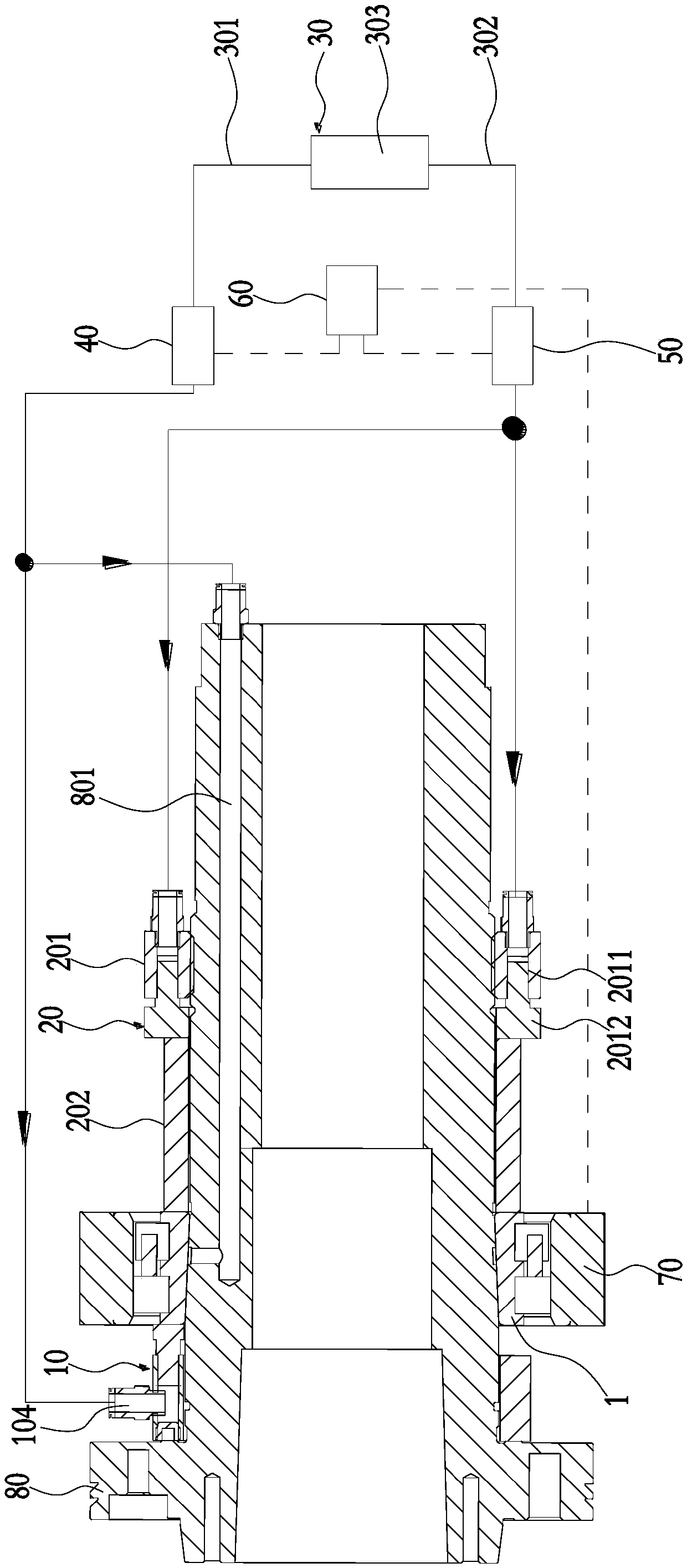
[0019] Such as figure 1 As shown, a device for adjusting bearing clearance includes a first pressing assembly 10, a second pressing assembly 20 and a hydraulic drive assembly 30. The first pressing assembly 10 has a first pressing portion for contact with the bearing 1 The inner ring at one end presses against each other, and the second pressing assembly 20 has a second pressing portion for pressing against the inner ring at the other end of the bearing 1. The hydraulic drive assembly 30 is connected with the first pressing assembly 10 and the second pressing assembly 10 respectively. The pressing assembly 20 is connected by transmission.

[0020] On...


PUM


Abstract

The invention discloses a device for adjusting the bearing clearance. The device comprises a first push-pressing assembly, a second push-pressing assembly and a hydraulic driving assembly, the first push-pressing assembly is provided with a first push-pressing part used for push-pressing the inner ring of one end of a bearing, and the second push-pressing assembly is provided with a second push-pressing part used for push-pressing the inner ring of the other end of the bearing. The hydraulic driving assembly is in transmission connection with the first push-pressing assembly and the second push-pressing assembly. When the device for adjusting the bearing clearance is used, the hydraulic driving assembly drives the first push-pressing assembly and the second push-pressing assembly to push-press the inner rings of the bearing so as to achieve the purpose that the bearing clearance is adjusted. Hydraulic transmission work is stable, thrust is huge, and the reliability and stability of thewhole bearing clearance are ensured accordingly; and compared with the traditional method that the inner ring of the bearing is directly knocked to adjust the bearing clearance, according to the device for adjusting the bearing clearance, parts in the bearing can be protected against damage, and the matching accuracy of the interior of the bearing is ensured.

Description

technical field [0001] The invention relates to the technical field of bearing clearance adjustment, in particular to a device and a main shaft for adjusting bearing clearance. Background technique [0002] The clearance of the bearing installed on the main shaft will affect the fatigue life, vibration and noise of the bearing. Therefore, when installing the bearing on the main shaft, it is often necessary to adjust the clearance of the bearing. At present, most manufacturers adjust the clearance between the inner and outer rings by directly tapping the inner ring of the bearing. Although this method of adjusting the bearing clearance is simple and the cost is not high, this adjustment method will directly It will cause damage to the bearing. The reason is that during the process of knocking the inner ring of the bearing, the vibration inertia caused by the strong vibration will cause the rollers of the bearing to collide with the raceway. Multiple strong knocks will also ca...

Claims


Application Information

Patent Timeline
Patent Type & Authority Applications(China)
IPC IPC(8): B23P19/00B23P19/10
CPCB23P19/00B23P19/10
Inventor 王哲汤秀清
Owner GUANGZHOU HAOZHI ELECTROMECHANICAL
Why Eureka
Try Eureka