Intelligent auxiliary control method applied to passenger vehicle blind area

An auxiliary control, blind spot technology, applied in vehicle components, optical observation devices, transportation and packaging, etc., can solve problems such as inability to make correct emergency judgments, increasing processor workload, and hindering the acceptance standards of automobile factory standards.

Inactive Publication Date: 2018-02-27
付绍航
View PDF4 Cites 3 Cited by
  • Summary
  • Abstract
  • Description
  • Claims
  • Application Information

AI Technical Summary

Problems solved by technology

It cannot be displayed on the screen in real time, it needs to be triggered, and BSD cannot work in real time
CN201020112040.2 A blind-spot-free driving visualization system requires infrared sensors to cooperate with displaying corresponding images, and cannot realize surround viewing and three-dimensional monitoring. It concentrates processing operations on the processor, thereby increasing the workload of the processor, thereby There is a reaction delay (about 3-5 seconds), and the reaction speed is slow. When the car is driving, the road conditions change rapidly. When the driver relies on the display screen, the reaction time is delayed here, and the correct emergency judgment cannot be made, resulting in traffic accidents
In addition, automobile manufacturers all adopt customized processes and production lines. This system is customized. For example, patent 201611059915.5 requires communication with automobile manufacturers and pre-installation, but it is not realistic in actual social life, which affects the appearance of the car. It is necessary to redesign the appearance of the car, the obstacle of the acceptance standard of the factory standard of the car, it is not beautiful, and cannot meet the individual requirements, and the driving habits of each driver are different

Method used


Image

  • Intelligent auxiliary control method applied to passenger vehicle blind area
  • Intelligent auxiliary control method applied to passenger vehicle blind area
  • Intelligent auxiliary control method applied to passenger vehicle blind area

Examples


Embodiment Construction

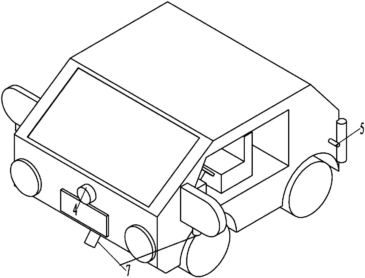
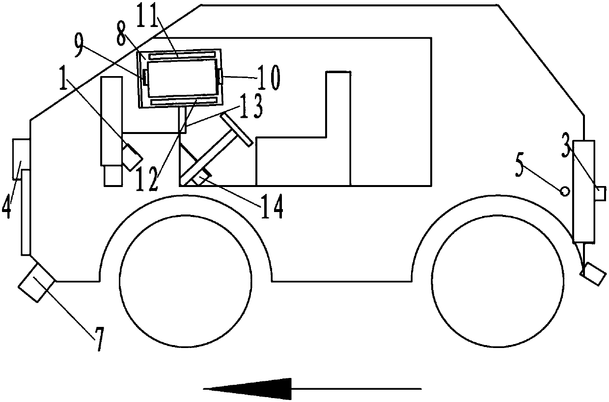
[0009] refer to Figure 1-11 As shown, the vehicle-mounted system for intelligent assistance in blind spots of passenger cars in this embodiment includes four or more than five blind spot camera modules 15 installed on the outside of the car and used to take pictures around the car;

[0010] The blind spot camera module 15 is one of the following two combinations:

[0011] Combination 1 includes a rear center camera 3 installed in the middle of the rear of the car and used to shoot the blind spot behind the car, and a front n-type camera system. The front middle camera 4 of A blind spot, the left front camera 5 that is installed on the left rear car outside and is used for photographing the left front B blind spot of the car, is installed on the right rear car outside and is used for photographing the right front camera 6 of the car right front D blind spot.

[0012] Combination 2, including the front center camera 4 installed in the middle of the front of the car and used to...


PUM


Abstract

The invention relates to an intelligent auxiliary control method applied to the blind area of ​​a passenger car, a display screen, a blind area camera module, a video switching logic controller, and an application processor implemented by means of split screens respectively installed on the automobile; comprising the following steps: 1. First, install the surround view camera module on the car, and then adjust the angle of view of each camera in the blind area camera module according to the car model and the surround view blind area of ​​the surround view camera module, so that the blind area formed by the angle of view of each camera is covered by the surround view blind area ; Step 2, at first, according to the vehicle action signal first through the trigger signal interface input signal to the video switching logic controller, the video switching logic controller then sets the control scheme of each camera in the blind spot camera module in the driving of the car according to the signal; Then, the application processor plays the camera content displayed by the control scheme on a single screen or in split screens in real time on the display screen; the invention has reasonable design, compact structure and convenient use.

Description

technical field [0001] The invention relates to an intelligent auxiliary control method applied to blind spots of passenger cars, and is particularly suitable for cars with less than 9 seats. Background technique [0002] With the increasing popularity of family cars in China, cars have become people's means of transportation. However, due to the blind spots of moving forward, turning and reversing in cars, the existing technology solves the problem through radar, or only by installing a camera on the rearview mirror. Realize all-round three-dimensional monitoring of the surrounding situation. Although the 360° surround view system such as patent 201611059915.5 is also used in high-end family cars, its viewing angle range is small and real-time dynamic monitoring cannot be realized. Although the prior patent ZL201610222471.6 discloses a vehicle-mounted system , but its structure is simple, unable to meet the needs of moving forward, turning, and real-time dynamic display. C...

Claims


Application Information

Patent Timeline
Patent Type & Authority Applications(China)
IPC IPC(8): B60R1/00
CPCB60R1/00B60R2300/105B60R2300/303B60R2300/607B60R2300/802
Inventor 付绍航付兵凯
Owner 付绍航
Why Eureka
Try Eureka