Construction method for excavating straight wall of rock deep foundation pit

A construction method and technology for deep foundation pits, which are applied in excavation, infrastructure engineering, construction, etc., can solve the problems of increasing the excavation range, increasing construction costs, and increasing the amount of backfilling, so as to reduce the amount of excavation engineering and reduce the amount of backfilling. The effect of reducing the amount of backfill usage

Inactive Publication Date: 2018-02-27
CHINA CONSTR 4TH ENG BUREAU 6TH
View PDF4 Cites 2 Cited by
  • Summary
  • Abstract
  • Description
  • Claims
  • Application Information

AI Technical Summary

Problems solved by technology

In the excavation process of this kind of foundation, power equipment is often used for breaking, such as large excavators, but it is difficult for power excavating equipment to control the construction accuracy of the excavation line due to the construction characteristics of the hydraulic breaking device, and the slope coefficient of 1:0.35 is often used. During excavation, the excavation area is often larger than the designed excavation area, and the load-bearing area to be retained during the excavation process is affected by the disturbance of the power equipment and excavation equipment to produce a loose layer. This loose layer will affect the bearing state of the foundation. Manual removal to dense areas not only wastes manpower and material resources, but also further increases the scope of excavation. The excess excavation area is backfilled with concrete, which increases the amount of backfill and leads to an increase in construction costs
Therefore, there is no better treatment method in this type of construction process at present

Method used


Image

  • Construction method for excavating straight wall of rock deep foundation pit
  • Construction method for excavating straight wall of rock deep foundation pit

Examples


Embodiment Construction

[0022] In order to make the purpose, technical solution and advantages of the present invention clearer, the present invention will be further described in detail below in conjunction with the accompanying drawings and embodiments.

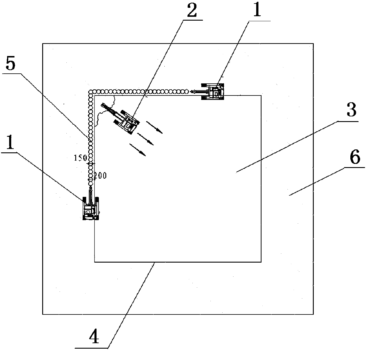
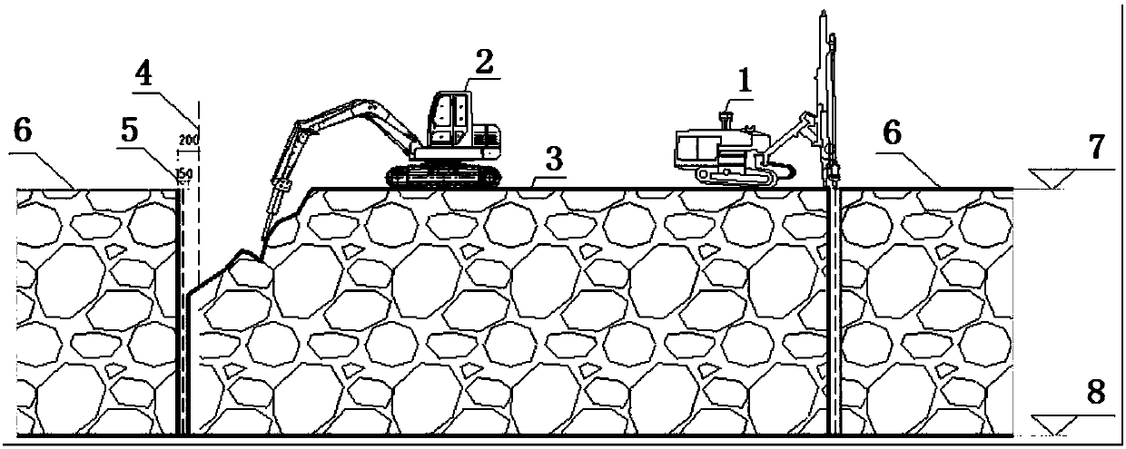
[0023] Embodiments of the invention: see figure 1 and figure 2 , the present invention is a kind of construction method that is used for the straight wall excavation of rock deep foundation pit, comprises the following steps:

[0024] Step 1. Sampling the excavation site to determine the range of rock hardness. The construction method of the present invention can be used within the scope of secondary hard rock, common hard rock and extra hard rock in the Platts Classification Table of Rock and Soil, and determine each hardness range in conjunction with the construction drawings. Excavation depth and scope of excavation in the area;

[0025] Step 2. Leveling the area to be excavated, and controlling the slope of the working surface within 1-10°;...


PUM

PropertyMeasurementUnit
Slopeaaaaaaaaaa

Abstract

The invention discloses a construction method for excavating a straight wall of a rock deep foundation pit. The construction method comprises the following steps of: adopting A KT5 type integrated open down-the-hole drill to excavate the straight wall of a rock surface of an excavating region continuously and vertically, wherein the precision is controlled high, the excavating sideline error rangeis controlled at 50mm, the vertical face vertical error is controlled within 5 degrees, the excavating depth is 1-10m, and separating zones which are 150m wide and are engaged one another are formedafter excavation, so that an excavating region and a bearing region are separated; crushing and clearing the excavating region by using a crushing excavator; reducing disturbance to a bearing foundation in the crushing and excavating process; and finally, leveling an arc and excavating the vertical face by way of plastering by a hung net to form a level waterproof construction basic layer. Therefore, the construction method has the characteristics that the integral excavated volume is reduced, the bearing capacity of the foundation is guaranteed, the construction efficiency is improved, the construction period is shortened, the construction operability is high, dust and noise pollution are reduced and the like, and the construction method can acquire relatively good economical and social benefits.

Description

technical field [0001] The invention relates to a construction method for straight wall excavation of deep rock foundation pits, and belongs to the technical field of foundation and foundation construction in construction engineering. Background technique [0002] In the construction process of super high-rise buildings, sub-hard stone, ordinary stone and extra-hard stone with high bearing capacity are often used as the main bearing carrier for the foundation, which has the physical characteristics of high bearing capacity and good integrity. In the excavation process of this kind of foundation, power equipment is often used for breaking, such as large excavators, but it is difficult for power excavating equipment to control the construction accuracy of the excavation line due to the construction characteristics of the hydraulic breaking device, and the slope coefficient of 1:0.35 is often used. During excavation, the excavation area is often larger than the designed excavat...

Claims


Application Information

Patent Timeline
IPC IPC(8): E02D17/02E02D17/04
CPCE02D17/02E02D17/04
Inventor 董浩
Owner CHINA CONSTR 4TH ENG BUREAU 6TH
Why Eureka
Try Eureka