
Rotary-support-based bank light structure

A technology of rotating support and support plate, which is applied to the parts of lighting devices, devices used in theaters and circuses, outdoor lighting, etc. , the effect of low wear

Active Publication Date: 2018-02-27
ANHUI MINGYANG ELECTRONICS
View PDF7 Cites 0 Cited by
  • Summary
  • Abstract
  • Description
  • Claims
  • Application Information

AI Technical Summary

Problems solved by technology

[0004] In order to overcome the above-mentioned technical problems, the purpose of the present invention is to provide a bar lamp structure based on rotating support. Through the cooperation of the cylindrical rod and the circular bottom hole and the cooperation of the rotating rod and the rotating block, Effectively ensure that the bar lights need 360° all-round without dead angle during operation, and at the same time, the fixed base, rotating base, rotating block and light frame are connected by the rotating rod and bolts, which solves the workload when the bar lights are disassembled and installed. Large and inefficient problems

Method used


Image

  • Rotary-support-based bank light structure
  • Rotary-support-based bank light structure
  • Rotary-support-based bank light structure

Examples


Embodiment Construction

[0031] The following will clearly and completely describe the technical solutions in the embodiments of the present invention with reference to the accompanying drawings in the embodiments of the present invention. Obviously, the described embodiments are only some, not all, embodiments of the present invention. Based on the embodiments of the present invention, all other embodiments obtained by persons of ordinary skill in the art without creative efforts fall within the protection scope of the present invention.

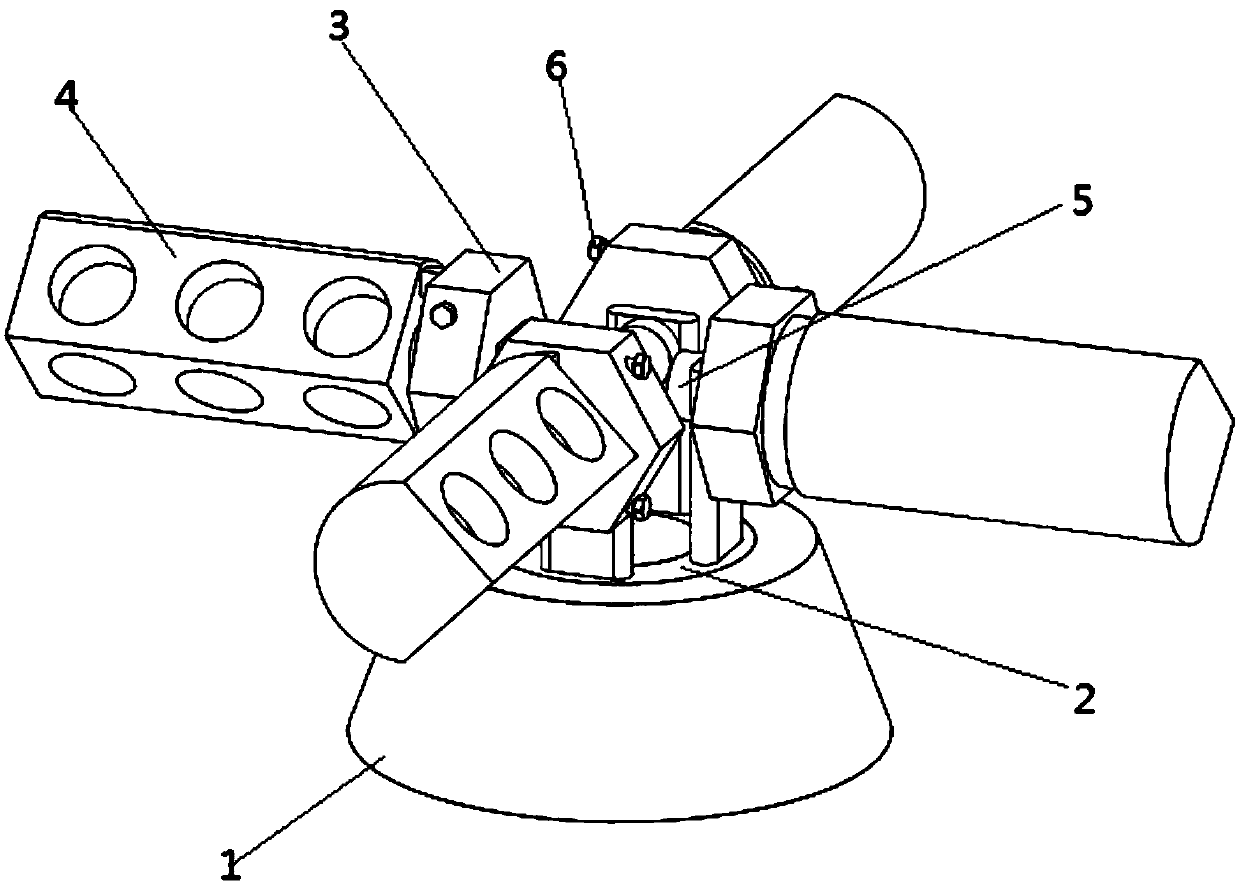
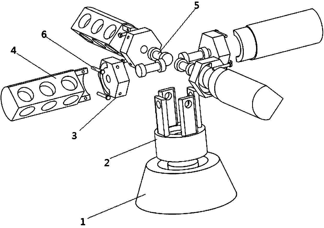
[0032] Such as figure 1 with figure 2 As shown, a bar lamp structure based on rotating support includes a fixed base 1 and a rotating base 2 connected in rotation with the fixed base 1. The rotating base 2 is connected with four rotating blocks 3 through a rotating rod 5, and the rotating blocks 3 pass through The bolt 6 is fixed with the lamp holder 4;

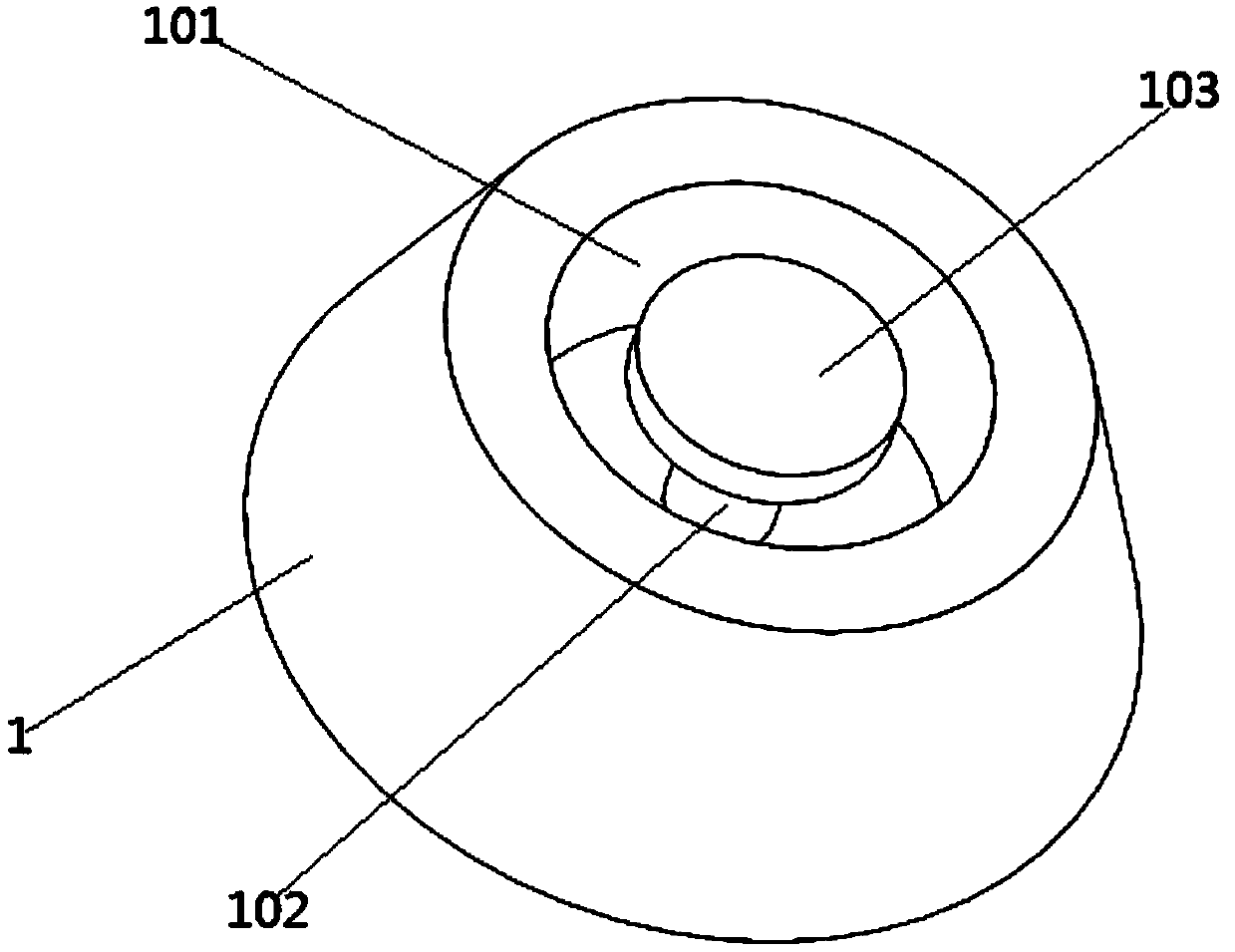
[0033] Such as image 3 As shown, the fixed base 1 is a cylinder with a narrow top and a wide bottom. The ...


PUM


Abstract

The invention discloses a rotary-support-based bank light structure. The rotary-support-based bank light structure comprises a fixed base and a rotary base rotatably connected with the fixed base. Therotary base is connected with four rotary clamping blocks through rotary rods. Light holders are fixed to the corresponding rotary clamping blocks through bolts. The fixed base is provided with a cylindrical clamping groove. A cylindrical rod is arranged at the bottom of the cylindrical clamping groove in a threaded fit mode. The upper end of the cylindrical rod is in threaded fit with a circularcover plate. The rotary base is provided with a cover plate groove matched with the circular cover plate. A circular bottom hole matched with the cylindrical rod is formed in the center of the bottomof the cover plate groove. Through cooperation of the cylindrical rod and the circular bottom hole and cooperation of the rotary rods and the rotary clamping blocks, 360-degree all-directional and no-dead-angle operation of a bank light is effectively guaranteed. Meanwhile, the fixed base, the rotary base, the rotary clamping blocks and the lamp holders are connected through the rotary rods and the bolts, and the problems of high workload and low efficiency of disassembling and assembling of the bank light are solved.

Description

technical field [0001] The invention belongs to the field of lamp manufacturing, and in particular relates to a row of lights, and more specifically to a row of lights structure based on a rotating support. Background technique [0002] Stage lighting is also called "stage lighting", or "lighting" for short. One of the means of stage art modeling. Using stage lighting equipment (such as lighting fixtures, slides, control systems, etc.) The external image of the stage performance, and provide the necessary lighting effects (such as wind, rain, cloud, water, lightning), etc. Stage lighting can be divided into floodlights, spotlights and slide lights according to the optical structure; according to the parts installed on the stage, there are surface lights, ear lights, foot lights, column lights, top lights, sky lights, ground lights and flow lights light. [0003] The row lights are high-power astigmatism lights, which are used to place on the stage, and the lower part of ...

Claims


Application Information

Patent Timeline
IPC IPC(8): F21S8/00F21V21/30F21V17/10F21V17/12F21W131/105F21W131/406
CPCF21S8/00F21V17/10F21V17/12F21V21/30F21W2131/105F21W2131/406
Inventor 陈敏
Owner ANHUI MINGYANG ELECTRONICS
Learn More