
Magnetic quantitative tipping bucket metering device

A technology of metering device and quantitative device, applied in the direction of fixed measuring room, etc., can solve the problems of large mechanical vibration and impact, affecting the life of the machine, complex mechanical structure, etc., and achieve the effect of no mechanical impact, long working life and accurate precision

Pending Publication Date: 2018-02-27
杭州飞科电气有限公司
View PDF8 Cites 1 Cited by
  • Summary
  • Abstract
  • Description
  • Claims
  • Application Information

AI Technical Summary

Problems solved by technology

The traditional tipping device will cause a large measurement error when the container wall is sticky with oil, and the mechanical vibration and impact of the two buckets turning back and forth are very large, which affects the life of the machine and cannot guarantee its long-term working reliability.
[0004] In response to the above defects, many improved tipping bucket metering devices have appeared on the market, among which the device described in the patent "CN205785383" is the most typical. By adding electronic sensors (such as weighing sensors), the effects of sticky oil and scaling on the bucket wall are eliminated. , because the electronic components of the sensor cannot be isolated from the medium, it is difficult for the electronic sensor to guarantee its life and measurement accuracy under the action of pressure, vibration, temperature, and oil and gas corrosiveness, and the device described in this patent still has mechanical contact, and the inside of the container The mechanical structure is too complex, and the life of the mechanical structural parts is difficult to guarantee

Method used


Image

  • Magnetic quantitative tipping bucket metering device

Examples


Embodiment Construction

[0016] Embodiments of the present invention will be described in further detail below in conjunction with the accompanying drawings.

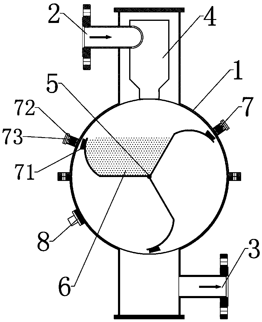
[0017] Such as figure 1 As shown, a magnetic quantitative tipping bucket metering device includes a container shell 1, a medium inlet 2 on the upper part of the container shell 1 and a medium outlet 3 on the lower part, and the medium inlet 2 communicates with the gas-liquid separation device 4 in the container shell 1 , the gas-liquid separation device 4 is a columnar swirl structure; the middle part of the container housing 1 is provided with at least three metering buckets 6 and magnetic quantitative devices 7 arranged at equal intervals that can rotate continuously around the central rotating shaft 5, and the surface of the metering bucket 6 is coated with anti- Corrosion anti-adhesive oil material, magnetic quantitative device 7 includes the magnet A71 that is located at the edge of the inner wall of the container housing 1 near the meteri...


PUM


Abstract

The invention provides a magnetic quantitative tipping bucket metering device, which comprises a container shell, a medium inlet in the upper part of the container shell and a medium outlet in the lower part of the container shell, wherein the medium inlet is communicated with a gas-liquid separation device in the container shell, at least three metering buckets and a magnetic quantitative deviceare arranged in the middle of the container shell, and the three metering buckets can continuously rotate around a central rotation axis and are arranged at equal intervals; the magnetic quantitativedevice comprises a magnet A, a magnet B and a position adjusting mechanism, the magnet A is arranged at an edge, close to an inner wall of the container shell, of the metering bucket, the magnet B isarranged on a corresponding outer wall of the container shell, the magnet A and the magnet B can generate interaction force, and the position adjusting mechanism can adjust the magnitude of the actionforce; a counting sensor is arranged on the outer wall of the container shell. The magnetic quantitative tipping bucket metering device disclosed by the invention has the advantages of simple structure, accurate precision, safety, reliability and no mechanical shock.

Description

technical field [0001] The invention relates to the technical field of fluid volume measurement, in particular to a magnetic quantitative tipping bucket measurement device. Background technique [0002] Tilting bucket metering is a more suitable method for wellhead fluid metering during oil production in oilfields. [0003] The traditional tipping bucket metering device such as the patent "CN204804824", the two container buckets flip back and forth to switch, and the liquid volume value is obtained by counting the number of flips. The traditional tipping device will cause a large measurement error when the container wall is sticky with oil, and the mechanical vibration and impact of the two buckets turning back and forth are very large, which affects the life of the machine and cannot guarantee its long-term working reliability. [0004] In response to the above defects, many improved tipping bucket metering devices have appeared on the market, among which the device descri...

Claims


Application Information

Patent Timeline
IPC IPC(8): G01F11/28
CPCG01F11/28
Inventor 王云平袁仕明李倩倩陈阳
Owner 杭州飞科电气有限公司
Learn More