
Dust deposition detecting and sensing unit, system and method

A technology of induction unit and detection system, which is applied in the direction of electromagnetic measuring device, electric/magnetic thickness measurement, instrument, etc., can solve problems such as production shutdown, fire source explosion, hidden safety hazard, etc., and achieve the effect of reducing vibration interference

Active Publication Date: 2018-02-27
CHINA COAL TECH ENG GRP CHONGQING RES INST
View PDF13 Cites 12 Cited by
  • Summary
  • Abstract
  • Description
  • Claims
  • Application Information

AI Technical Summary

Problems solved by technology

[0002] In production dust workplaces such as polishing and grinding workshops, large grain processing plants, stone and wood processing plants, in order to avoid dust occupational hazards and dust explosion accidents, the production dust must be dedusted. Dust collectors are generally used to remove dust Carry out dust removal treatment; but it brings safety hazards: the dust deposition in the dust removal pipeline will produce a violent explosion when there is an ignition source (such as static electricity, friction sparks, etc.), which will bring very serious harm
[0003] At present, there is no effective method for the detection of dust deposited in pipelines. The State Administration of Work Safety's "Five Regulations on Strictly Preventing Dust Explosions in Enterprises" stipulates that "the ventilation and dust removal system must be designed, installed, used and maintained in accordance with standard specifications, and each shift shall be tested according to regulations. It is strictly forbidden to operate during the shutdown period of the dust removal system and when the dust exceeds the standard, and stop production and evacuate personnel.” The standard stipulates that when the deposition thickness exceeds 1mm, it must be cleaned.

Method used


Image

  • Dust deposition detecting and sensing unit, system and method
  • Dust deposition detecting and sensing unit, system and method
  • Dust deposition detecting and sensing unit, system and method

Examples


Embodiment Construction

[0046] Embodiments of the present invention are described in detail below, examples of which are shown in the drawings, wherein the same or similar reference numerals designate the same or similar elements or elements having the same or similar functions throughout. The embodiments described below by referring to the figures are exemplary only for explaining the present invention and should not be construed as limiting the present invention.

[0047] In the description of the present invention, unless otherwise specified and limited, it should be noted that the terms "installation", "connection" and "connection" should be understood in a broad sense, for example, it can be mechanical connection or electrical connection, or two The internal communication of each element may be directly connected or indirectly connected through an intermediary. Those skilled in the art can understand the specific meanings of the above terms according to specific situations.

[0048] The inventio...


PUM


Abstract

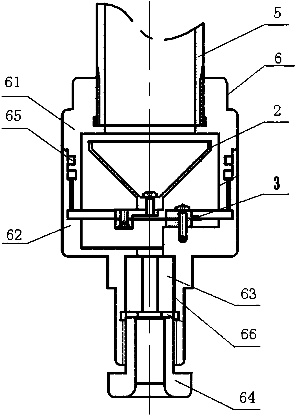
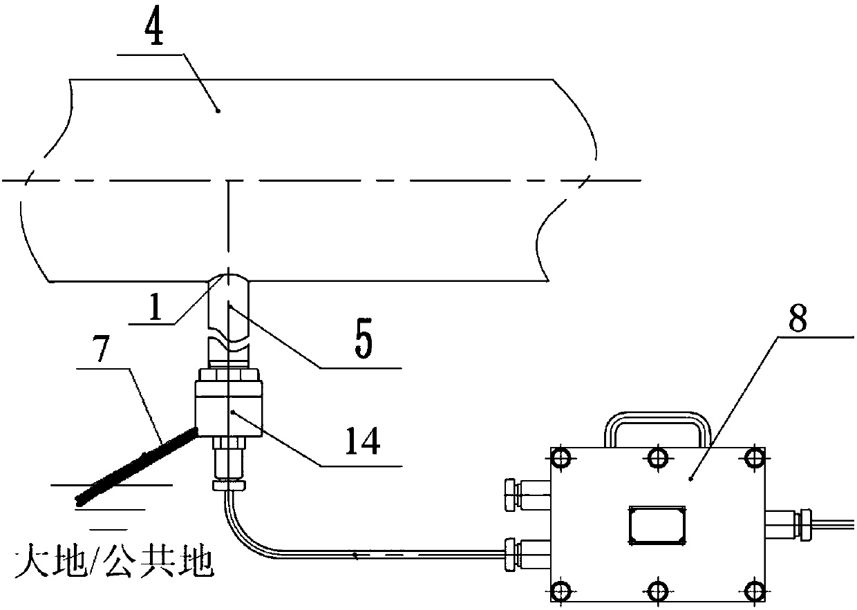
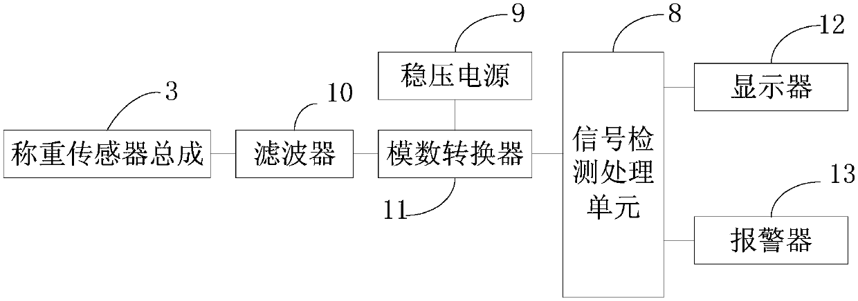
The invention discloses a dust deposition detecting and sensing unit, system and method. The dust deposition detecting and sensing unit comprises a detecting hole, a dust accumulating hopper and a weighing sensor assembly, wherein the detecting hole is formed in the bottom of a dust collection pipeline; the dust accumulating hopper is used for accumulating the dust depositing at the bottom of thedust collection pipeline; the bottom of the dust accumulating hopper is in contact connection with a weighing surface of the weighing sensor assembly; the sensing unit can realize online continuous monitoring and does not require separate weight test after dust collection, so as to monitor the dust thickness on the dust collection pipeline in real time. Signals output by a weighing sensor are processed by filtering, analog-digital conversion, moving average, singular value removal, vibration interference removal and the like, thus the influence on the test result caused by the vibration interference from the complicated test environment and the creep property of the weighing sensor is reduced, average dust thickness of unit area in the dust collection pipeline can be tested accurately, andthe prediction of dust explosion can be realized.

Description

technical field [0001] The invention relates to the field of dust detection, in particular to a dust deposition detection sensing unit, system and method. Background technique [0002] In production dust workplaces such as polishing and grinding workshops, large grain processing plants, stone and wood processing plants, in order to avoid dust occupational hazards and dust explosion accidents, the production dust must be dedusted. Dust collectors are generally used to remove dust Carry out dust removal treatment; but it brings safety hazards: the dust deposition in the dust removal pipeline will produce a violent explosion when there is an ignition source (such as static electricity, friction sparks, etc.), which will bring very serious hazards. [0003] At present, there is no effective method for the detection of dust deposited in pipelines. The State Administration of Work Safety's "Five Regulations on Strictly Preventing Dust Explosions in Enterprises" stipulates that "th...

Claims


Application Information

Patent Timeline
IPC IPC(8): G01N5/02G01N15/04G01B7/06
CPCG01B7/06G01N5/02G01N15/04
Inventor 吴付祥张强张少华刘国庆陈建阁王杰李德文焦敏赵政邓勤惠立锋李征真罗小博晏丹王俊庭
Owner CHINA COAL TECH ENG GRP CHONGQING RES INST
Learn More