[0018] In order to make the technical means, creative features, objectives and effects of the present invention easy to understand, the present invention will be further explained below in conjunction with specific embodiments.
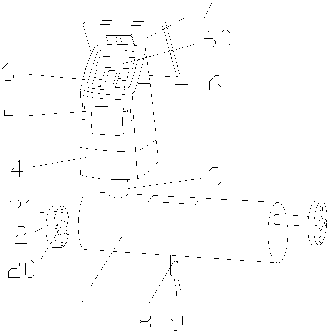
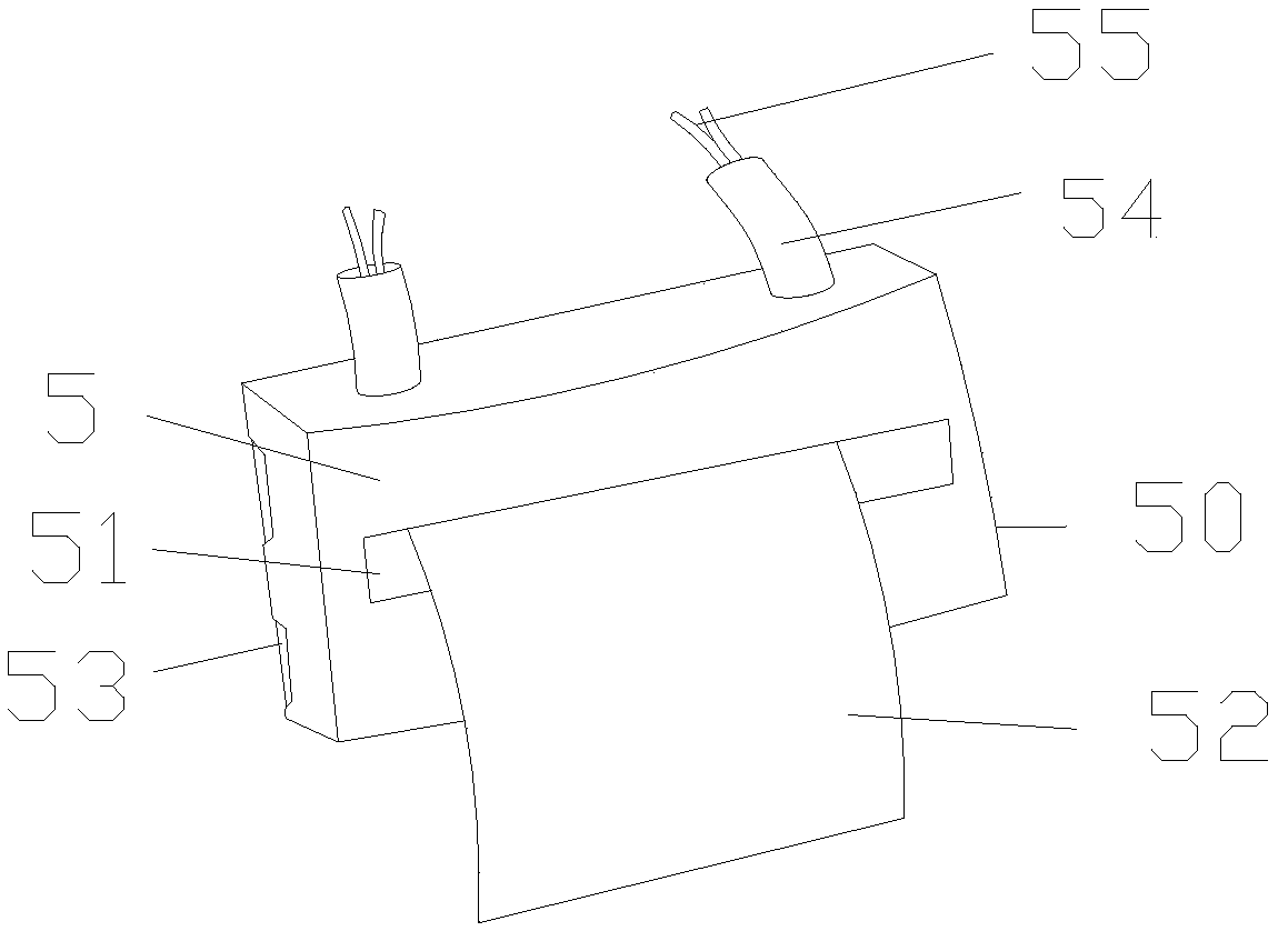
[0019] See Figure 1-Figure 2 , The present invention provides an intelligent sewage treatment and detection device based on solar energy. Its structure includes a detection pool 1, a feed inlet 2, a support column 3, an intelligent detection head 4, a data printing outlet 5, an automation controller 6, and a solar panel 7. , Fastening block 8, locking frame 9, the feed port 2 is fixedly welded to the left end surface of the detection pool 1, the support column 3 is vertically connected to the middle of the upper end surface of the detection pool 1, and the intelligent detection head 4 Fixedly connected to the upper surface of the support column 3, the data printing outlet 5 is electrically connected to the middle of the front end surface of the intelligent detection head 4, and the data printing outlet 5 consists of the main body 50 of the printing device, the printing paper outlet 51, the printing paper 52, The printing nozzle 53, the terminal 54 and the connecting wire 55 are composed. The printing paper outlet 51 is embedded in the front end surface of the printing device main body 50, and the printing paper 52 is movably connected to the front end surface of the printing paper outlet 51. The printing device main body 50 is provided with a cavity, the printing nozzle 53 is electrically connected to the internal cavity of the printing device body 50, the terminal 54 is vertically connected to the upper surface of the printing device body 50, and the connecting wire 55 is movably connected On the upper end surface of the terminal 54, the data printing outlet 5 is connected to the intelligent detection head 4 through a connecting line 55, the automation controller 6 is electrically connected to the upper end surface of the intelligent detection head 4, and the solar panel 7 It is movably connected to the middle of the upper end surface of the intelligent detection head 4, the fastening block 8 is welded perpendicularly to the middle of the lower end surface of the detection cell 1, and the locking frame 9 is movably connected to the front end surface of the fastening block 8. The left end surface of the feed port 2 is fixedly welded with a connecting disk 20. The outer surface of the connecting disk 20 is embedded with connecting holes 21. The number of connecting holes 21 is 8 and they are evenly distributed on the edge of the outer surface of the connecting disk 20. At the upper part of the front surface of the automation controller 6, a display screen 60 is inlaid, and the lower part of the front surface of the automation controller 6 is movably connected with a control button 61 through a keyway. The number of the control buttons 61 is 6 and they are even The print nozzles 53 are equally spaced on the lower part of the front end surface of the automation controller 6, and the number of the print nozzles 53 is 2-3. They are evenly spaced in the internal cavity of the printing device body 50, and they are mutually In a parallel state, the shape of the solar panel 7 is a rectangular parallelepiped with a width of 200-250 mm, and it is electrically connected to the smart detection head 4.
[0020] The data printing outlet mentioned in this patent has high printing accuracy. In general, the ink can be replaced with one of the colors of ink separately, instead of the inkjet printers of the early years. As long as one of the colors of ink is used up, it needs to be combined with the remaining colors. Replace them together, causing waste.
[0021] When in use, first check whether each part is firmly connected. After confirming that the equipment is in good condition, place the equipment in a suitable position, connect the feed inlet of the equipment to the treated sewage, adjust the automation controller of the equipment, and turn on the data printer of the equipment. , Then the device can start to work normally.
[0022] The detection pool-1, feed inlet-2, support column-3, intelligent detection head-4, data printing outlet-5, automation controller-6, solar panels-7, fastening blocks-8, locks of the present invention Tightening frame-9, printing device body-50, printing paper outlet-51, printing paper-52, printing nozzle-53, terminal-54, connecting wire-55, connecting plate-20, connecting hole-21, display screen- 60. The control button-61, the parts are all general standard parts or parts known to those skilled in the art, and their structure and principles are all known to those skilled in the technical manual or through conventional experimental methods. Problems solved by the present invention It is that in the process of detecting sewage treatment results in the prior art, important detection information and data cannot be printed in a timely and fast manner, which may cause the detection results to not be displayed to users in a popular and intuitive manner, and the practical performance is insufficient. Through the combination of the above components and the data printing outlet, the important detection information and data can be printed in time and quickly during the detection of the sewage treatment results, so that the detection results can be displayed in a popular and intuitive manner. For users, it is convenient for subsequent data analysis and statistics, which effectively improves the practical performance of the equipment, as follows:
[0023] The data printing outlet 5 is electrically connected to the middle of the front end surface of the intelligent detection head 4. The data printing outlet 5 is composed of the printing device main body 50, the printing paper outlet 51, the printing paper 52, the printing nozzle 53, the terminal 54 and the connection The printing paper outlet 51 is embedded in the front end surface of the printing device main body 50, the printing paper 52 is movably connected to the front end surface of the printing paper outlet 51, and the printing device main body 50 is provided with a cavity inside. The printing nozzle 53 is electrically connected to the internal cavity of the printing device body 50, the terminal 54 is vertically connected to the upper surface of the printing device body 50, and the connecting wire 55 is movably connected to the upper surface of the terminal 54. The data printing outlet 5 is connected to the intelligent detection head 4 through a connecting line 55.
[0024] In Embodiment 1 of the present invention, the number of print nozzles is 2, and the width of the solar panel is 200 mm; in Embodiment 2 of the present invention, the number of print nozzles is 3, and the solar panel The width of the board is 250 mm.
[0025]
[0026] In summary, when the number of print nozzles of the present invention is 3 and the width of the solar panel is 250 mm, the data printing quality of the data printing outlet of the present invention is better, and the quality of solar power supply reaches the best state.
[0027] The above shows and describes the basic principles and main features of the present invention and the advantages of the present invention. For those skilled in the art, it is obvious that the present invention is not limited to the details of the above exemplary embodiments, and does not deviate from the spirit or basics of the present invention. In the case of features, the present invention can be implemented in other specific forms. Therefore, from any point of view, the embodiments should be regarded as exemplary and non-limiting. The scope of the present invention is defined by the appended claims rather than the foregoing description, and therefore it is intended to fall within the claims. All changes within the meaning and scope of equivalent elements of are included in the present invention. Any reference signs in the claims should not be regarded as limiting the claims involved.
[0028] In addition, it should be understood that although this specification is described in accordance with the implementation manners, not each implementation manner only includes an independent technical solution. This narration in the specification is only for clarity, and those skilled in the art should consider the specification as a whole The technical solutions in the embodiments can also be appropriately combined to form other implementations that can be understood by those skilled in the art.