Workpiece surface spraying device

A spraying device and a technology on the surface of workpieces, applied in the field of machinery, can solve the problems of affecting the service life of the sleeve, increasing the process, increasing labor intensity, etc., achieving good economic and social benefits, ensuring the effect of operation, and reducing the use of manpower

Active Publication Date: 2018-03-02
雷震
View PDF5 Cites 13 Cited by
  • Summary
  • Abstract
  • Description
  • Claims
  • Application Information

AI Technical Summary

Problems solved by technology

Because it is set on various wrenches and shaped like a tube, it is commonly called a sleeve. It is a commonly used tool for production, maintenance, and life. The socket wrench is made of multiple hexagonal or twelve-angled holes The sleeve is equipped with a variety of accessories such as handles and extension rods. It is especially suitable for screwing bolts or nuts that are very narrow or deeply recessed. The sleeve will produce a lot of waste debris and rust on the lower surface after long-term use. , it needs to be re-sprayed to ensure its service life. The existing outer wall of the sleeve is mostly sprayed by the operator with a spraying device to spray the sleeve. After spraying, the waste and impurities need to be removed, which increases the process and improves the efficiency. Labor intensity, at the same time, during the use of hand-held spraying, some dead angles will not be sprayed or the amount of spraying will be low, which will greatly affect the service life of the sleeve

Method used


Image

  • Workpiece surface spraying device
  • Workpiece surface spraying device
  • Workpiece surface spraying device

Examples


Embodiment Construction

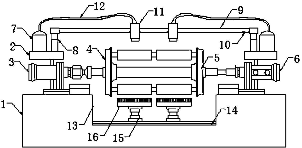
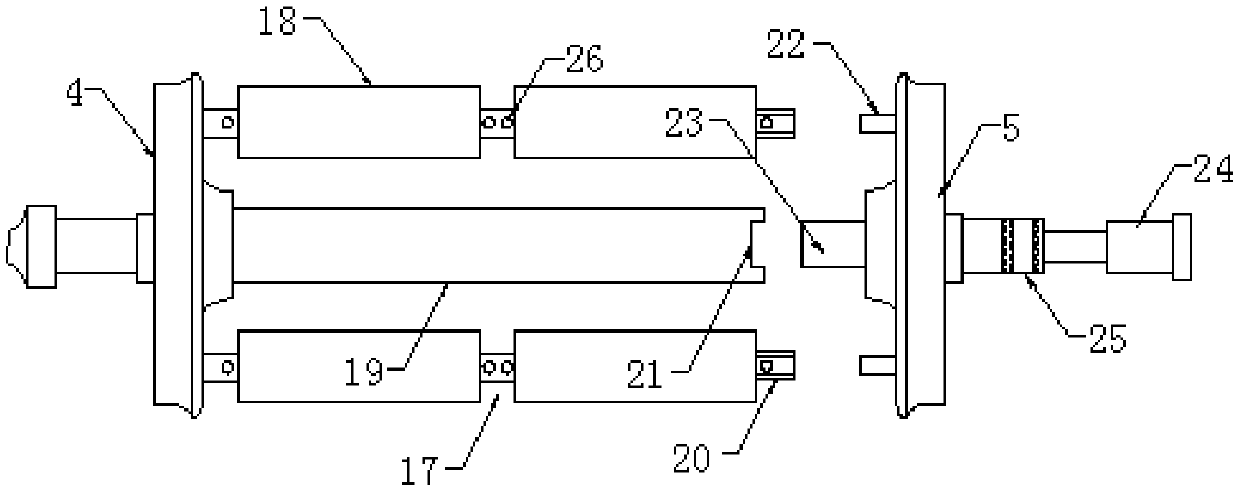
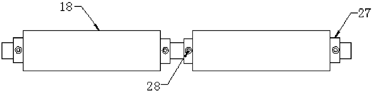
[0021] Such as Figure 1-3 As shown, this specific embodiment adopts the following technical solutions: a workpiece surface spraying device, including a workbench 1, a frame 2, a drive motor 3, a rotating seat 4, a support seat 5, a hydraulic cylinder 6, a storage tank 7, a lifting Frame 8, beam 9, slide rail 10, high pressure nozzle 11, infusion tube 12, groove 13, chute 14, lifting base 15, brush head 16, mounting frame 17, workpiece 18, fixing frame 19, mounting frame bayonet 20 , fixed frame bayonet 21, mounting frame pressure head 22, fixed frame pressure head 23, hydraulic rod 24, movable joint head 25, positioning hole 26, snap ring 27 and limit pin 28, and a groove 13 is provided on the workbench 1 , the workbench 1 on both sides of the groove 13 is equipped with a frame 2, and the two ends of the workbench 1 are respectively fixed with a drive motor 3 and a hydraulic cylinder 6 through the frame 2, and a lifting frame 8 is installed on the frame 2. A crossbeam 9 is f...


PUM


Abstract

The invention discloses a workpiece surface spraying device. The workpiece surface spraying device comprises a worktable, racks, a driving motor, a rotating seat, a supporting seat, a hydraulic cylinder, storage cylinders, lifting frames, a cross beam, a sliding rail, high-pressure spray heads, liquid transferring pipes, a groove, a sliding groove, lifting bases, brush heads, mounting frames, workpieces, a fixing frame, mounting frame bayonets, a fixing frame bayonet, mounting frame pressure heads, a fixing frame pressure head, a hydraulic rod, a movable connector, positioning holes, clampingrings and limiting pins. The workpiece surface spraying device is compact in structure, convenient to use and capable of conducting surface spraying operation on the multiple sleeve workpieces simultaneously, and the service life of the workpieces is prolonged; meanwhile, the surfaces of the workpieces can be subjected to impurity removing before being sprayed, so that the situation that the operation effect is affected by excessive impurities and dust is avoided, using is convenient, and the various using requirements in the spraying process of the workpieces are met; and the workpiece surface spraying device is used flexibly overall, uniform spraying is achieved, the working efficiency is high, high practicability is achieved, the operation effect is guaranteed, and using of manpower iseffectively reduced.

Description

Technical field: [0001] The invention relates to the field of mechanical technology, in particular to a workpiece surface spraying device. Background technique: [0002] Socket is the abbreviation of socket wrench. Because it is set on various wrenches and shaped like a tube, it is commonly called a sleeve. It is a commonly used tool for production, maintenance, and life. The socket wrench is made of multiple hexagonal or twelve-angled holes The sleeve is equipped with a variety of accessories such as handles and extension rods. It is especially suitable for screwing bolts or nuts that are very narrow or deeply recessed. The sleeve will produce a lot of waste debris and rust on the lower surface after long-term use. , it needs to be re-sprayed to ensure its service life. The existing outer wall of the sleeve is mostly sprayed by the operator with a spraying device to spray the sleeve. After spraying, the waste and impurities need to be removed, which increases the process a...

Claims


Application Information

Patent Timeline
Patent Type & Authority Applications(China)
IPC IPC(8): B05B13/02B05B13/04B08B1/00B08B1/02B08B13/00
CPCB05B13/0228B05B13/041B08B1/002B08B1/02B08B13/00
Inventor 雷震
Owner 雷震
Why Eureka
Try Eureka