
Glass-cutting apparatus

A glass cutting and other side technology, applied in the direction of glass cutting devices, glass manufacturing equipment, manufacturing tools, etc., can solve the problems of delayed working time, reduced working efficiency, reduced working efficiency, etc., to reduce working time and prolong service life , the effect of improving work efficiency

Inactive Publication Date: 2018-03-02
ZHONGSHAN CHUANGKE RES TECH SERVICE
View PDF0 Cites 10 Cited by
  • Summary
  • Abstract
  • Description
  • Claims
  • Application Information

AI Technical Summary

Problems solved by technology

[0002] Nowadays, a lot of glass needs to be used in construction. The glass cutting device used in construction is just a cutting knife connected to a motor to work, or a cutting knife can be used for cutting, but the glass used in construction needs glass of various sizes, which requires work. Personnel measure the required size on the glass and then cut it, which is very troublesome and reduces work efficiency
When cutting very long glass, the staff is cutting with a wooden board in hand, which is prone to shaking, resulting in irregular cutting and waste, and it is also prone to safety hazards, and it is necessary to draw lines on the glass when cutting the glass. Only in this way can we ensure that the cutting will be a straight line, but the manual operation will have a large error, which will easily affect the later use, and a large amount of debris will fall on the glass plate or workbench during the cutting process, and the staff needs to be constantly To clean up, seriously delaying working time and reducing work efficiency

Method used


Image

  • Glass-cutting apparatus
  • Glass-cutting apparatus
  • Glass-cutting apparatus

Examples


Embodiment Construction

[0021] Below in conjunction with accompanying drawing and specific embodiment the present invention is described in further detail:

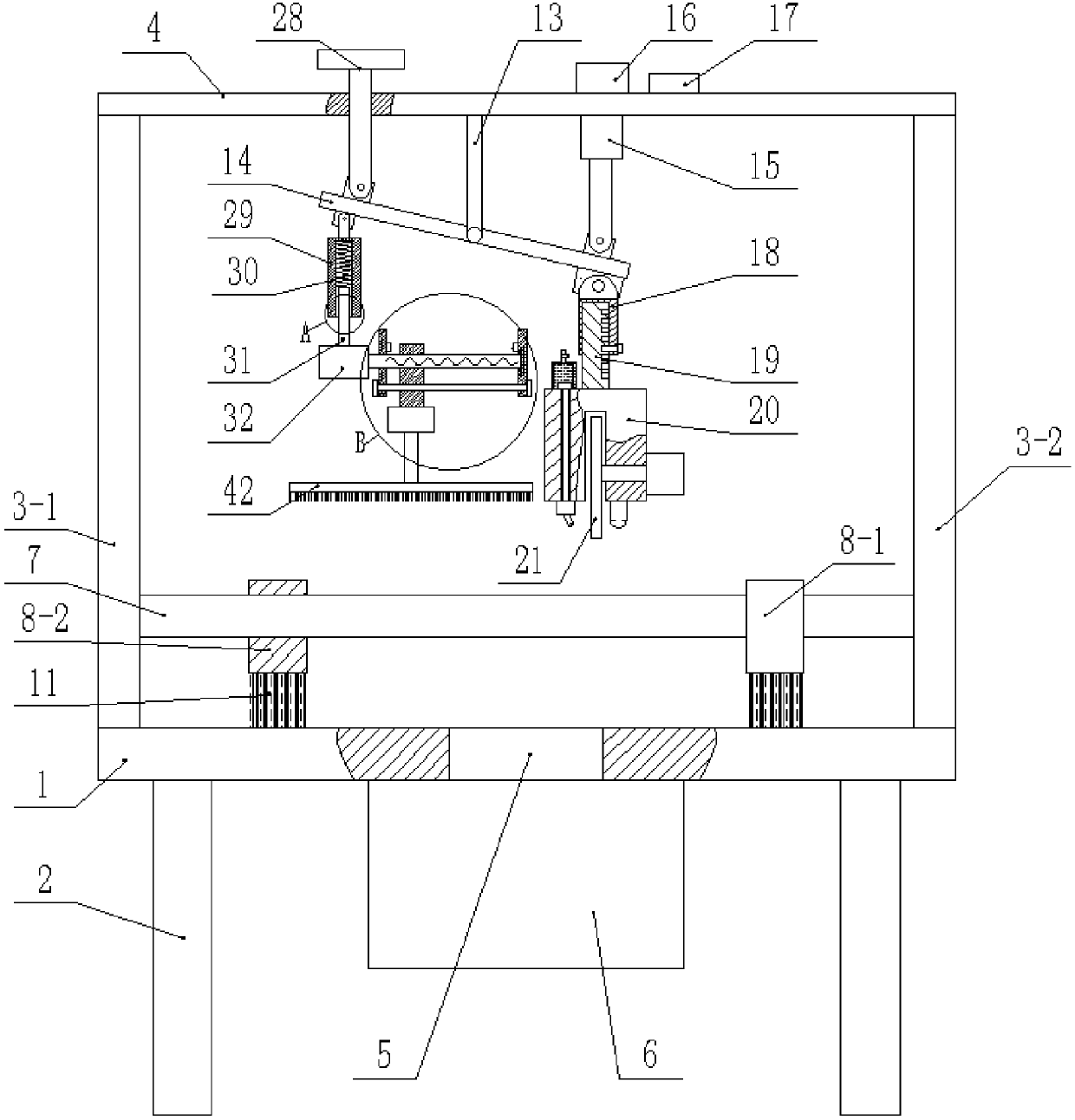
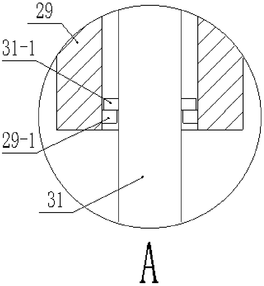
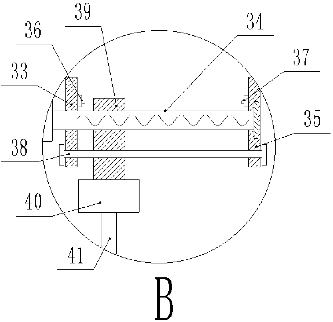
[0022] Such as figure 1 , figure 2 , image 3 , Figure 4 , Figure 5 , Image 6As shown, a glass cutting device includes a workbench 1, four legs 2 are fixedly arranged at the bottom of the workbench 1, a through hole 5 is provided in the center of the workbench 1, and a There is a recovery box 6, the recovery box 6 is arranged at the bottom of the through hole 5 and communicates with it, the two side edges on the top surface of the workbench 1 are fixed with a square bracket A3-1 and a square bracket B3-2, the Square support A3-1 and square support B3-2 top are fixedly connected with fixed plate 4, described square support A3-1 and square support B3-2 are symmetrically fixedly connected with slide bar 7 by going out through the bottom end, slide bar 7 is provided with There is a scale line, the slide bar 7 is slidably connected with a s...


PUM


Abstract

The invention discloses a glass cutting device, which comprises a workbench, four legs are fixedly arranged at the bottom of the workbench, a through hole is arranged in the center of the workbench, a recovery box is fixedly arranged on the bottom surface of the workbench, and the recovery box is arranged in the through hole. The bottom of the hole is in communication with it. Square bracket A and square bracket B are fixed on both sides of the top surface of the workbench. The top of square bracket A and square bracket B is fixedly connected with a fixing plate. The bottom end is symmetrically fixedly connected with a slide bar. The present invention is convenient for workers to cut glass of different sizes, shapes and thicknesses, and does not need to be manually measured or operated by hands, which ensures the safety of the cutting device, and can achieve positioning and cutting straight lines, and the cutting knife Cool down, prolong its service life, and can clean the debris on the glass after cutting, which effectively reduces the working time of the staff, thus greatly improving the work efficiency.

Description

technical field [0001] The invention relates to the field of glass cutting, in particular to a glass cutting device. Background technique [0002] Nowadays, a lot of glass needs to be used in construction. The glass cutting device used in construction is just a cutting knife connected to a motor to work, or a cutting knife can be used for cutting, but the glass used in construction needs glass of various sizes, which requires work. Personnel measure the required size on the glass and then cut it, which is very troublesome and reduces work efficiency. When cutting very long glass, the staff is cutting with a wooden board in hand, which is prone to shaking, resulting in irregular cutting and waste, and it is also prone to safety hazards, and it is necessary to draw lines on the glass when cutting the glass. Only in this way can we ensure that the cutting will be a straight line, but the manual operation will have a large error, which will easily affect the later use, and a la...

Claims


Application Information

Patent Timeline
IPC IPC(8): C03B33/02
CPCC03B33/02
Inventor 粟婷鲍芳秦文锋杨永华
Owner ZHONGSHAN CHUANGKE RES TECH SERVICE
Learn More