Special locking device for high-low voltage cabinets

A locking device, a technology for high and low voltage cabinets, applied in the field of high and low voltage switch cabinets, can solve the problems of easy loss of keys, hidden safety hazards of buckles, troublesome management of key locks, etc.

Inactive Publication Date: 2018-03-02
合肥智鼎电控自动化科技有限公司
View PDF6 Cites 7 Cited by
  • Summary
  • Abstract
  • Description
  • Claims
  • Application Information

AI Technical Summary

Problems solved by technology

[0003] Among them, most of the existing high and low voltage switch cabinets are locked by traditional key locks or buckles. The traditional key locks are very troublesome to manage and the keys are easy to lose, and the buckles have potential safety hazards.

Method used


Image

  • Special locking device for high-low voltage cabinets
  • Special locking device for high-low voltage cabinets

Examples


Embodiment Construction

[0015] Below in conjunction with embodiment the present invention will be further described, but the present invention is not limited to these examples, under the premise of departing from the gist of the present invention, any improvement made falls within the protection scope of the present invention.

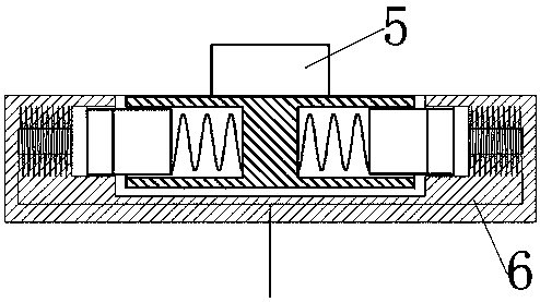
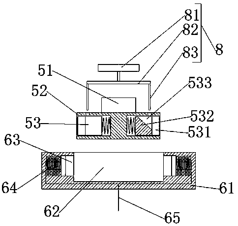
[0016] As shown in the figure, a special locking device for high and low voltage cabinets according to the present invention includes a spring locking structure 5 and an electromagnetic locking structure 6. The spring locking structure 5 includes a connecting part 51 and a The cylindrical portion 52, the two ends of the cylindrical portion are provided with an impermeable circular hole 1, and the circular holes 1 at the two ends are provided with movable pins 53, and the movable pins 53 are connected by a spring and a circle. The bottom of the shaped hole is connected, and the movable pin is completely located in the circular hole when the spring has no external force. The ele...


PUM


Abstract

A special locking device for high-low voltage cabinets comprises a spring locking structure and an electromagnetic locking structure. The spring locking structure comprises a connecting portion and acylindrical portion vertical to the connecting portion, two ends of the cylindrical portion are provided with first dead circular holes, and movable pins are respectively disposed in the first circular holes at the two ends. The electromagnetic locking structure comprises a fixed block, one side of the fixed block is provided with a U-shaped notch cooperated with the cylindrical portion, two endsof the U-shaped notch are provided with second circular holes cooperated with the movable pins, and the bottoms of the second circular holes at the two ends are respectively provided with electromagnet structures. Deficiency of the prior art is overcome, the special locking device comprises the spring locking structure and the electromagnetic locking structure, the movable pins in the spring locking structure are pulled by springs and contracted in the cylindrical portion under a normal condition, when a door is closed, the movable pins are cooperated with the electromagnetic locking structure, attracted by the electromagnets in the electromagnetic locking structure and inserted into the electromagnetic locking structure so as to lock the door, and when the door is required to be opened, electromagnet current is cut off by a control switch. The special locking device is simple in operation and wide in application range.

Description

technical field [0001] The invention relates to the technical field of high and low voltage switch cabinets, in particular to a special locking device for high and low voltage cabinets. Background technique [0002] The high and low voltage switchgear is a kind of electrical equipment. The outside line first enters the main control switch in the cabinet, and then enters the sub-control switch. Each branch is set according to its needs. Such as instruments, automatic control, motor magnetic switches, various AC contactors, etc., some also have high-voltage room and low-voltage room switch cabinets, high-voltage busbars, such as power plants, etc. load shedding. [0003] Among them, most of the existing high and low voltage switch cabinets are locked by traditional key locks or buckles. The traditional key locks are very troublesome to manage and the keys are easy to lose, and the buckles have potential safety hazards. Contents of the invention [0004] The purpose of the ...

Claims


Application Information

Patent Timeline
Patent Type & Authority Applications(China)
IPC IPC(8): E05B47/06E05B65/02E05B65/52H02B1/30
CPCE05B47/0603E05B47/0004E05B65/02E05B65/5223H02B1/30
Inventor 罗永康赵松朱棣吴亚军
Owner 合肥智鼎电控自动化科技有限公司
Why Eureka
Try Eureka