Detection device and sleep state monitor

A technology for detection devices and detection areas, which is applied in the direction of measuring devices, instruments, scientific instruments, etc., and can solve the problems such as the inconvenience of infrared sensor partition cycle detection

Active Publication Date: 2018-03-02
SHUCHENG HONGYE HARDWARE & PLASTIC PROD
View PDF7 Cites 3 Cited by
  • Summary
  • Abstract
  • Description
  • Claims
  • Application Information

AI Technical Summary

Problems solved by technology

[0003] In view of this, the purpose of the embodiments of the present invention is to provide a detection device and a sleep state monitor to solve the problem of inconvenient circular detection of infrared sensors.

Method used


Image

  • Detection device and sleep state monitor
  • Detection device and sleep state monitor
  • Detection device and sleep state monitor

Examples


no. 1 example

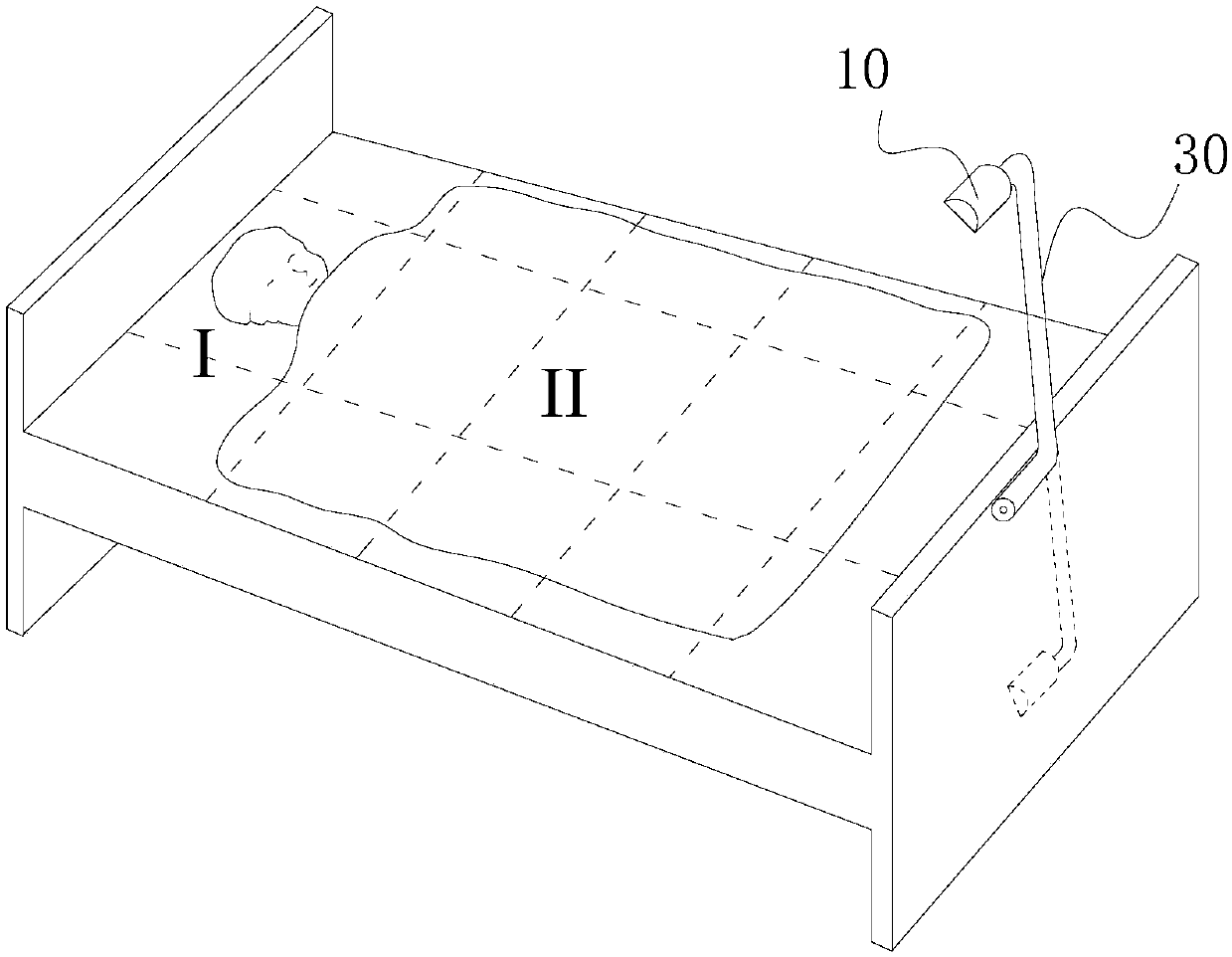
[0029] Children often kick the quilt during sleep, kicking off the quilt is easy to catch cold, but the guardian cannot keep an eye on the child during sleep. In order to solve this problem, the embodiment of the present invention provides a sleep state monitor. When in bed, the temperature of multiple parts of the bed can be collected and analyzed to determine whether the child is kicking the quilt.

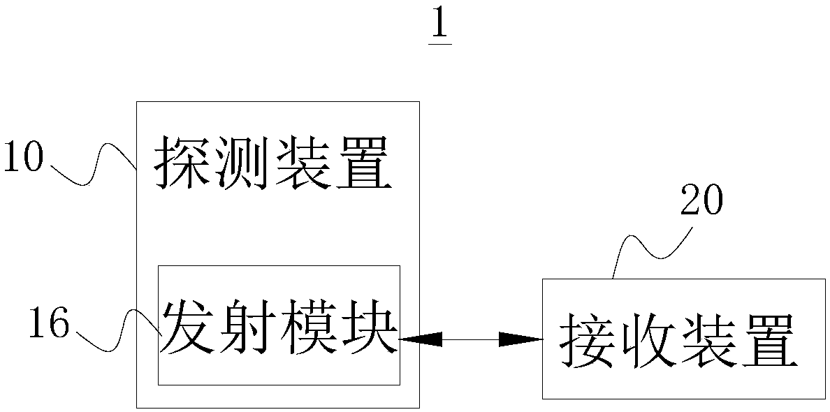
[0030] Please refer to figure 1 with figure 2 , figure 1 It is the application environment diagram of the sleep state monitor provided by the first embodiment of the present invention, figure 2 It is an interaction diagram of the detection device 10 and the receiving device 20 of the sleep state monitor 1 provided by the first embodiment of the present invention. The sleep state monitor 1 of present embodiment comprises detecting device 10 and receiving device 20 (as mobile phone), and this detecting device 10 is arranged on the end of bed by support bar 30, certainly also ...

no. 2 example

[0051] Please refer to Image 6 , is a schematic structural diagram of the detection device 10 provided by the second embodiment of the present invention. This embodiment provides an implementation of the detection area control mechanism 12 that enables the infrared sensor 11 to detect line by line. The detection area control mechanism 12 includes a support frame 1213, and the shape of the support frame is a hexahedron. To sum up, the support frame can also be other, such as a cylinder and the like.

[0052] The detection area control mechanism 12 includes a liquid crystal screen 1212, and the liquid crystal screen 1212 and the infrared sensor 11 are arranged on two opposite surfaces of the support frame, so that the liquid crystal screen 1212 is located between the infrared sensor 11 and the bed surface to be detected. In this embodiment , the detection range of the infrared sensor 11 can cover the entire liquid crystal screen 1212 . The liquid crystal screen 1212 is provid...

no. 3 example

[0056] Please refer to Figure 7 , is a schematic structural diagram of the detection device 10 provided by the third embodiment of the present invention. This embodiment provides an implementation of the detection area control mechanism 12 that enables the infrared sensor 11 to detect line by line. Installed on the PCB board 1211 , the PCB board 1211 is set on the pan-tilt 1223 , and the pitch driving motor can also be set on the pan-tilt 1223 . The horizontal angle drive motor 1221 is used to control the rotation of the pan-tilt 1223 in the horizontal direction, and the pitch angle drive motor 1222 is used to control the pitch angle of the infrared sensor 11 in the vertical direction.

[0057] Specifically, the horizontal angle driving motor 1221 is connected with a horizontal angle driving shaft (not shown in the figure), and the end of the horizontal angle driving shaft away from the horizontal angle driving motor 1221 is fixedly connected with a horizontal angle driving ...


PUM


Abstract

The embodiment of the invention provides a detection device and a sleep state monitor, and relates to the technical field of computer vision monitoring. The sleep state monitor includes the detectiondevice and a receiving device. The detection device includes an infrared sensor and a detection area control mechanism. The infrared sensor is configured to obtain the temperature information of a detection area. The detection area control mechanism is configured to adjust the detection area of the infrared sensor by a motor or a liquid crystal screen. The detection device also includes a transmitting module and is wirelessly connected to the receiving device through the transmitting module. The detection area control mechanism adjusts the detection area of the infrared sensor of the detectiondevice so that the detection device can accurately detect the temperatures in different areas of a bed, accurately determines whether a child kicks off a quilt, and send an alarm signal to remind a guardian to timely deal with the situation.

Description

technical field [0001] The invention relates to the technical field of computer vision monitoring, in particular to a detection device and a sleep state monitor. Background technique [0002] When a child is sleeping, he often kicks the quilt and catches a cold easily. It is impossible for the guardian to stare at the child sleeping all the time. There are already a lot of detection equipment for kicking quilts on the market, but most of them are based on traditional temperature measuring sensors, and most of them are installed in quilts. By measuring whether the temperature of the quilt drops to achieve the purpose of judging whether the child kicks the quilt, but the device needs to be It is inconvenient to put it inside the quilt, but setting it outside the quilt to detect the temperature is not easy to control and inaccurate. Therefore, the problem of detecting the temperature of the child's quilt in a partition cycle to detect the child's sleep state needs to be solved ...

Claims


Application Information

Patent Timeline
Patent Type & Authority Applications(China)
IPC IPC(8): G01J5/00G01J5/02
CPCG01J5/00G01J5/0025G01J5/0205G01J5/0275G01J5/48
Inventor 陈健
Owner SHUCHENG HONGYE HARDWARE & PLASTIC PROD
Why Eureka
Try Eureka