Device and method for verifying secondary voltage dividing plate parameter of high-voltage DC voltage divider

A DC voltage divider, high voltage DC technology, applied in the direction of measuring devices, instruments, measuring electrical variables, etc., can solve problems such as the inability to perform overall calibration, and achieve the effect of significant economic benefits

Active Publication Date: 2018-03-02
EXAMING & EXPERIMENTAL CENT OF ULTRAHIGH VOLTAGE POWER TRANSMISSION COMPANY CHINA SOUTHEN POWER GRID
View PDF12 Cites 0 Cited by
  • Summary
  • Abstract
  • Description
  • Claims
  • Application Information

AI Technical Summary

Problems solved by technology

[0005] The invention overcomes the defect that the secondary voltage divider plate of the DC voltage divider cannot be checked as a whole when it is disassembled, and provides a test device for simulating the actual wiring mode of the DC voltage divider to verify the parameters of the secondary voltage divider plate

Method used


Image

  • Device and method for verifying secondary voltage dividing plate parameter of high-voltage DC voltage divider
  • Device and method for verifying secondary voltage dividing plate parameter of high-voltage DC voltage divider
  • Device and method for verifying secondary voltage dividing plate parameter of high-voltage DC voltage divider

Examples


Embodiment 1

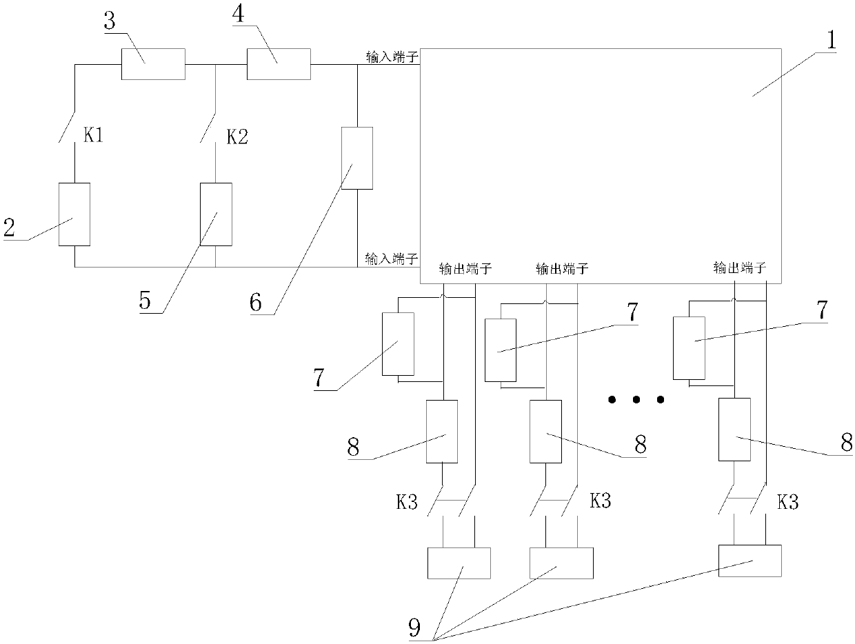
[0023] Such as figure 1 As shown, a high-voltage DC voltage divider secondary voltage divider parameter verification device, the secondary voltage divider 1 is used to perform a secondary transformation ratio on the voltage at both ends of the low-voltage arm of the DC voltage divider, and the calibration The test device includes a DC constant voltage source 2 for generating the DC voltage required for calibration, a first current transformer 3 for measuring the output current of the DC constant voltage source 2, and a first current transformer 3 for measuring the input current of the secondary voltage divider 1 The second current transformer 4 is used to measure the first voltage transformer 5 of the DC voltage between the input terminals of the secondary voltage divider 1, and the first variable resistor 6 used for the low-voltage arm resistance of the equivalent DC voltage divider is used The second voltage transformer 7 for measuring the DC voltage between the output termi...

Embodiment 2

[0025] A method for verifying the parameters of a secondary voltage divider plate 1 of a high-voltage DC voltage divider, wherein the secondary voltage divider plate 1 is used to perform a secondary transformation ratio on the voltage at both ends of the low-voltage arm of the DC voltage divider, such as figure 1 As shown, it includes a DC constant voltage source 2 for generating the DC voltage required for calibration, a first current transformer 3 for measuring the output current of the DC constant voltage source 2, and a first current transformer 3 for measuring the input of the secondary voltage divider board 1 The second current transformer 4 for current, the first voltage transformer 5 for measuring the DC voltage between the input terminals of the secondary voltage divider 1, the first variable resistor 6 for the low-voltage arm resistance of the equivalent DC voltage divider, The second voltage transformer 7 for measuring the DC voltage between the output terminals of t...


PUM


Abstract

A device for verifying a secondary voltage dividing plate parameter of a high-voltage DC voltage divider includes a DC constant-voltage source for generating verification-required DC voltage; a firstcurrent transformer for measuring the output current of the DC constant-voltage source; a second current transformer for measuring the input current of a secondary voltage dividing plate; a first voltage transformer for measuring the DC voltage between the input terminals of the secondary voltage dividing plate, a first variable resistor equivalent to the low-voltage arm resistor of the DC voltagedivider; a second voltage transformer for measuring the DC voltage between the output terminals of the secondary voltage dividing plate; a third current transformer for measuring the output current of the secondary voltage dividing plate; and a second variable resistor equivalent to the internal resistance of an optoelectronic module of the DC voltage divider. The device can correctly simulate the input and output resistance and transformation ratio of the voltage dividing plate under the actual connection mode of the DC voltage divider, is helpful to verifying the characteristic parameters of the secondary voltage dividing plate and discovering the defects of the secondary voltage dividing plate timely, and has great economic benefits.

Description

technical field [0001] The invention relates to the field of DC system voltage measurement, in particular to a parameter calibration of a secondary voltage divider plate of a DC voltage divider. Background technique [0002] The DC voltage divider is an important and core voltage monitoring device in the UHV converter station. Its function is to realize the real-time monitoring of the DC voltage of the converter station and feed back the monitoring results to the DC control system. It affects and determines the control of the DC project. Protection strategy and operation mode. Once the DC voltage divider fails, it will cause a unipolar blockage of the DC system, or cause the entire DC transmission system to shut down, which will significantly increase the operation risk of the power grid and may cause huge economic losses. [0003] A DC voltage divider generally includes a body, a secondary voltage divider and a photoelectric conversion module. The main body is composed of...

Claims


Application Information

Patent Timeline
Patent Type & Authority Applications(China)
IPC IPC(8): G01R35/02
CPCG01R35/02Y02E60/60
Inventor 卢文浩刘婉莹韦晓星王奇
Owner EXAMING & EXPERIMENTAL CENT OF ULTRAHIGH VOLTAGE POWER TRANSMISSION COMPANY CHINA SOUTHEN POWER GRID
Why Eureka
Try Eureka