In-hole shear wave source and method for testing wave speed by using cross-hole method

An internal shear and source technology, applied in the engineering field, can solve the problems of small excitation energy, limited travel of the support plate, and difficulty in inflating the airbag, and achieve the effects of accurate trigger time, precise trigger signal, and increased effective propagation distance.

Pending Publication Date: 2018-03-02
河北中核岩土工程有限责任公司
View PDF0 Cites 2 Cited by
  • Summary
  • Abstract
  • Description
  • Claims
  • Application Information

AI Technical Summary

Problems solved by technology

The in-hole seismic source is a key equipment for the cross-hole wave velocity test. The following two types of equipment are usually used. One is a hydraulic wall-supported shear hammer, which has a large supporting force in the hole, but the travel of the support plate is limited. Rock drilling and soil drilling cannot be reliably adhered to the wall; the other is the airbag wall-attached shear hammer. Although it is applicable to a wide range of apertures, it is difficult and easy to inflate the airbag in drilling holes with well fluid. air leak problem
Both have the problem of small excitation energy. When the drilling distance is large or the elastic modulus of rock and soil is large, and large excitation energy is required, the requirements are often not met.

Method used


Image

  • In-hole shear wave source and method for testing wave speed by using cross-hole method
  • In-hole shear wave source and method for testing wave speed by using cross-hole method
  • In-hole shear wave source and method for testing wave speed by using cross-hole method

Examples


Embodiment Construction

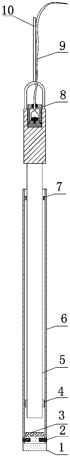
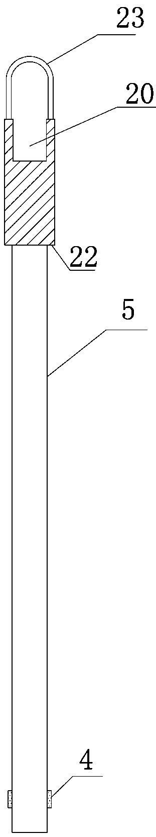
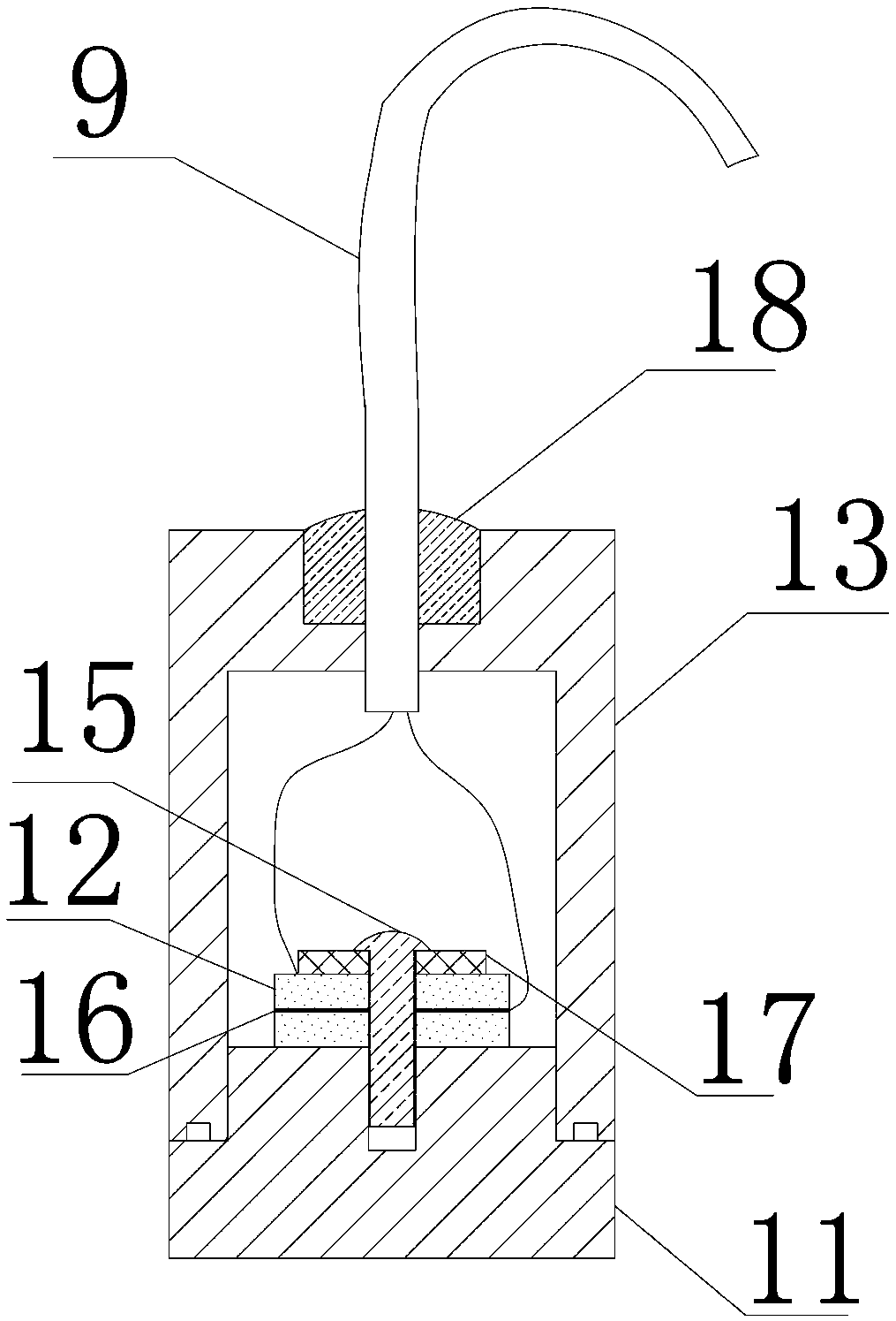
[0027] as attached Figure 1-4 As shown, the in-hole shear wave seismic source of the present invention includes a guide cylinder 6, a columnar weight 5 arranged in the guide cylinder 6, a hammer pad 1 fixed on the lower end of the guide cylinder 6 by bolts A, and a hammer pad 1 arranged on the upper end of the weight 5. The trigger 8 connected with the ground wave velocity tester inside; the heavy hammer 5 is a solid cylindrical hammer body made of stainless steel, and a nylon gasket 3 is arranged on the top surface of the hammer pad 1; Water tank; a limit device is set in the guide cylinder 6 and on the weight 5, the limit device limits the falling and rising positions of the weight 5, and a load-bearing ring 23 is fixedly installed on the top of the weight 5, and the load-bearing The ring 23 is connected with the anti-rotation steel wire rope 10, and the other end of the anti-rotation steel wire rope 10 is fixedly connected with the support 30 installed on the ground.

[0...


PUM


Abstract

The invention relates to a shear wave seismic source in a hole and a method for testing wave velocity by cross-hole method. The shear wave seismic source in a hole includes a guide cylinder, a weight, a hammer pad and a trigger; a limit device is arranged in the guide cylinder and on the weight , the anti-rotation steel wire rope is arranged at the top of the weight; the method of the present invention adopts the steps of construction of the receiving hole and the excitation hole, the hammer pad and the bottom of the excitation hole in close contact and calculating the propagation velocity of the shear wave; the trigger of the present invention is installed on the weight The top ensures the accuracy of the trigger time; the test method is highly adaptable and can be used for rock drilling or soil drilling; the excitation energy is large, the effective signal is strong, and the effective propagation distance of the shear wave is long.

Description

technical field [0001] The invention relates to a shear wave seismic source in a hole and a wave velocity testing method of a cross-hole method, belonging to the field of engineering technology. Background technique [0002] The cross-hole wave velocity test is an important means to test the shear wave velocity, compression wave velocity, dynamic shear modulus, dynamic elastic modulus and dynamic Poisson's ratio of rock and soil in geotechnical engineering investigation. The in-hole seismic source is a key equipment for the cross-hole wave velocity test. The following two types of equipment are usually used. One is a hydraulic wall-supported shear hammer, which has a large supporting force in the hole, but the travel of the support plate is limited. Rock drilling and soil drilling cannot be reliably adhered to the wall; the other is the airbag wall-attached shear hammer. Although it is applicable to a wide range of apertures, it is difficult and easy to inflate the airbag in...

Claims


Application Information

Patent Timeline
Patent Type & Authority Applications(China)
IPC IPC(8): G01V1/147G01V1/02G01V1/42
CPCG01V1/147G01V1/159G01V1/42G01V2210/1216G01V2210/1299G01V2210/1429G01V2210/6222
Inventor 陈小峰苏铁军李玉良田永杰胡胜波
Owner 河北中核岩土工程有限责任公司
Why Eureka
Try Eureka