Thread end burying spacing electric adjustment mechanism and method for adjusting thread end burying spacing using same

A technology of electric adjustment and transmission mechanism, which is applied in the direction of conductive pattern formation, etc., can solve the problems of increasing the work intensity of operators, reducing the comprehensive utilization rate of equipment, and difficult to guarantee the accuracy, so as to improve the utilization rate of equipment, increase the self-weight of the equipment, shorten the The effect of adjusting the time

Pending Publication Date: 2018-03-02
BEIJING GOLDEN SPRING TECH DEV
View PDF1 Cites 2 Cited by
  • Summary
  • Abstract
  • Description
  • Claims
  • Application Information

AI Technical Summary

Problems solved by technology

The sheet layout has precision requirements for parameters such as the distance between adjacent coils, the distance from the first coil to the edge of the sheet, and the line spacing. In the industry, the mechanical structure of the embedding component is usually used to adjust the distance between adjacent coils. This adjustment The method has high requirements on the proficiency of the operator, and the adjustment time is long, and the accuracy is not easy to guarantee. After each adjustment of the position of the embedding head assembly, it is necessary to use raw materials for testing and adjustment. When the operator is not skilled, it may use a large number of Testing and adjustment of materials to be produced
Therefore, in the production process of the multi-head embedding machine, every time the layout of the sheet is changed, it will take tens of minutes to several hours to adjust the distance between the embedding heads, which greatly reduces the comprehensive utilization of the equipment and increases the work of the operator. strength, reducing work efficiency

Method used


Image

  • Thread end burying spacing electric adjustment mechanism and method for adjusting thread end burying spacing using same
  • Thread end burying spacing electric adjustment mechanism and method for adjusting thread end burying spacing using same
  • Thread end burying spacing electric adjustment mechanism and method for adjusting thread end burying spacing using same

Examples


Embodiment Construction

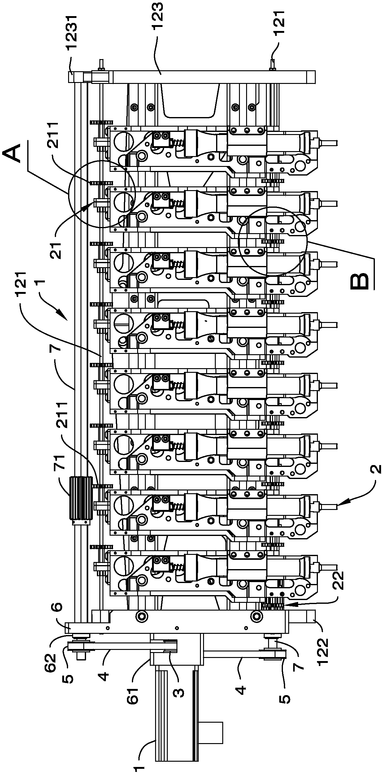
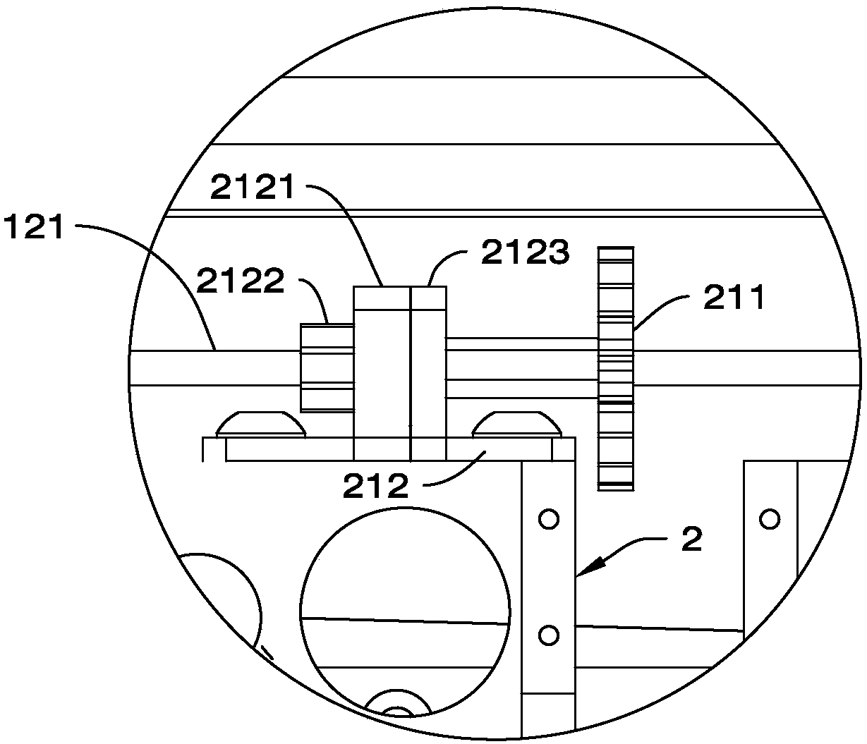
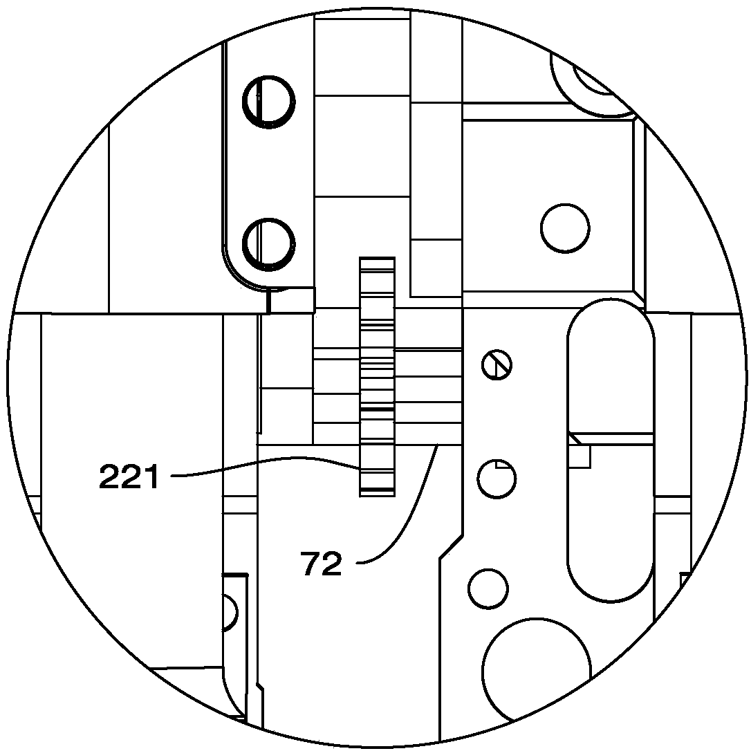
[0042] Such as figure 1 As shown, the thread embedding head spacing electric adjustment mechanism of the present invention includes a thread embedding head adjusting device 1, and two transmission shafts 7 arranged in parallel up and down and with large gears 71, 72 are installed on the thread embedding head adjusting device 1, and the large gears 71, 72 are coaxial The rotation is installed on the transmission shaft 7, and the two transmission shafts 7 are all driven to rotate by the motor-synchronous pulley transmission mechanism. An upper bull gear 71 is installed on the transmission shaft 7 above, and a lower bull gear 72 is installed on the transmission shaft 7 below. preferred, such as Figure 14 to Figure 17 As shown, the cross section of the transmission shaft 7 is a special-shaped quadrilateral. The special-shaped quadrilateral is spliced ​​by a rectangle and two circular arcs with the same length and curvature but opposite bending directions. The two circular arcs a...


PUM


Abstract

The invention discloses a thread end burying spacing electric adjustment mechanism, which includes a thread end burying adjustment device and a plurality of thread end burying assemblies that are mounted on a multi-end thread burying machine and can translate along a straight line. When the mechanism is used to adjust the thread end burying spacing, the mechanism is first mounted on a thread burying part of the multi-end thread burying machine, large gears on drive shafts are manually slid to mesh with adjustment gears on adjustment assemblies, then a moving distance value is input into a control system, and the large gears on the drive shafts are driven to rotate through a motor-synchronous pulley drive mechanism, so as to drive the thread end burying assembly to move to a predetermined position on a screw; and next, the large gears are slid along the drive shafts to next adjustment gears of the thread end burying assembly to be displaced, the large gears are meshed with the adjustment gears, and the above steps are repeated until the adjustment of the position of all the thread end burying assemblies is completed. The purpose of the invention is to provide the thread end buryingspacing electric adjustment mechanism with a shorter thread end burying spacing adjustment time, higher precision and simple operation, and a method for adjusting the thread end burying spacing usingthe same.

Description

technical field [0001] The invention relates to a device for thread embedding, glue dispensing and welding on a base material, in particular to an electric adjustment mechanism for the distance between thread embedding heads and a method for adjusting the distance between thread embedding heads using the same. Background technique [0002] At present, multi-head embedding machines often need to be compatible with multiple sheet layouts, and the coil positions of each sheet layout and the distance between two adjacent coils are different. Therefore, when the sheet layout produced by the multi-head embedding machine changes, The new sheet layout can only be adapted by adjusting the position of the hardware (embedding assembly). The sheet layout has precision requirements for parameters such as the distance between adjacent coils, the distance from the first coil to the edge of the sheet, and the line spacing. In the industry, the mechanical structure of the embedding component...

Claims


Application Information

Patent Timeline
Patent Type & Authority Applications(China)
IPC IPC(8): H05K3/10
CPCH05K3/10
Inventor 张晓冬
Owner BEIJING GOLDEN SPRING TECH DEV
Why Eureka
Try Eureka