
Metal comb of textile tube forward-backward laser cutting mechanism

A cutting mechanism and textile tube technology, applied in the field of metal combs, can solve the problems of inaccurate laser cutting, inability to meet design requirements, unreasonable structural design, etc., and achieve the effect of accurate cutting

Pending Publication Date: 2018-03-06
浙江克鲁森纺织科技有限公司
View PDF0 Cites 0 Cited by
  • Summary
  • Abstract
  • Description
  • Claims
  • Application Information

AI Technical Summary

Problems solved by technology

Current laser cutting devices can only cut textile tubes on one side
Moreover, due to the unreasonable structural design of the current laser cutting mechanism, the laser cutting is inaccurate and cannot meet the design requirements.

Method used


Image

  • Metal comb of textile tube forward-backward laser cutting mechanism

Examples


Embodiment Construction

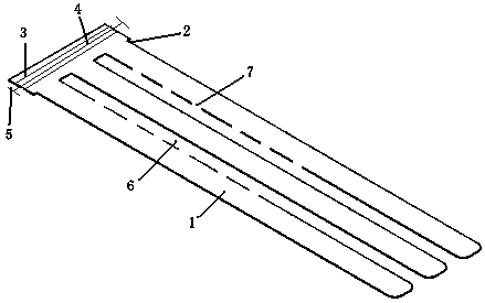
[0009] Combine below figure 1 Specific description embodiment:

[0010] The metal comb of the positive and negative laser cutting mechanism of the textile tube is characterized in that it includes a comb body 1, and the two sides of the head end of the comb body 1 are provided with locking grooves 2, and the head end of the comb body is provided with a concave Groove 3, the spring 4 is arranged in the groove, and the two ends of the spring are connected with the contact plate 5; the tail end of the comb body is opened, and two cutting grooves 6 are opened on the comb body.

[0011] Preferably, several positioning notches 7 are provided on both sides of the cutting groove.


PUM


Abstract

The invention belongs to the technical field of tools used for textile tube forward-backward laser cutting, and particularly relates to a metal comb of a textile tube forward-backward laser cutting mechanism. The metal comb of the textile tube forward-backward laser cutting mechanism is characterized in that the metal comb comprises a comb body, position clamping grooves are formed in the two sides of the head end of the comb body, a groove is formed in the position of the head end of the comb body, a spring is arranged in the groove, and the two ends of the spring are connected with contact plates; and an opening is formed in the tail end of the comb body, and two cutting grooves are formed in the comb body. The metal comb has the beneficial effects that two-side cutting is conducted on products, and cutting is precise.

Description

technical field [0001] The invention belongs to the technical field of front and back laser cutting tools for textile tubes, in particular to a metal comb for a front and back laser cutting mechanism for textile tubes. Background technique [0002] In the production process of the current textile tube, it is necessary to carry out laser cutting on the textile tube. Current laser cutting devices can only cut textile tubes on one side. Moreover, due to the unreasonable structural design of the current laser cutting mechanism, the laser cutting is inaccurate and cannot meet the design requirements. Contents of the invention [0003] The purpose of the present invention is to solve the above-mentioned technical problems, and to provide a metal comb with a front and back laser cutting mechanism for textile tubes that can cut products on both sides and cut accurately. The technical solution is as follows: [0004] The metal comb of the positive and negative laser cutting mecha...

Claims


Application Information

Patent Timeline
IPC IPC(8): B23K26/38
CPCB23K26/38
Inventor 姚浩杰徐飞飞张金燕朱顺忠沈丽丽顾伟叶胡盼盼梁彬邵国武
Owner 浙江克鲁森纺织科技有限公司
Learn More