Mounting rod and manufacturing method thereof
A technology for installing rods and rod bodies, applied in the field of installation rods, can solve the problems of strong local pressure and profile damage, and achieve the effects of high strength, good strength and various process structures.
- Summary
- Abstract
- Description
- Claims
- Application Information
AI Technical Summary
Problems solved by technology
Method used
Image
Examples
Embodiment 1
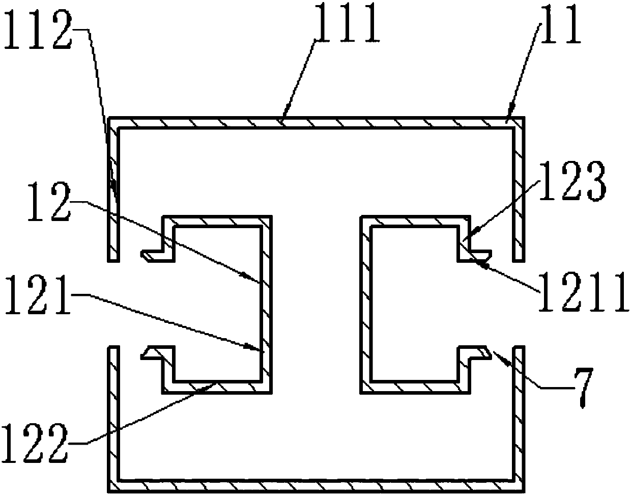
[0063] The rod body in Embodiment 1 of the present invention includes such as figure 2 The cross-sectional structure of the mounting rod shown.
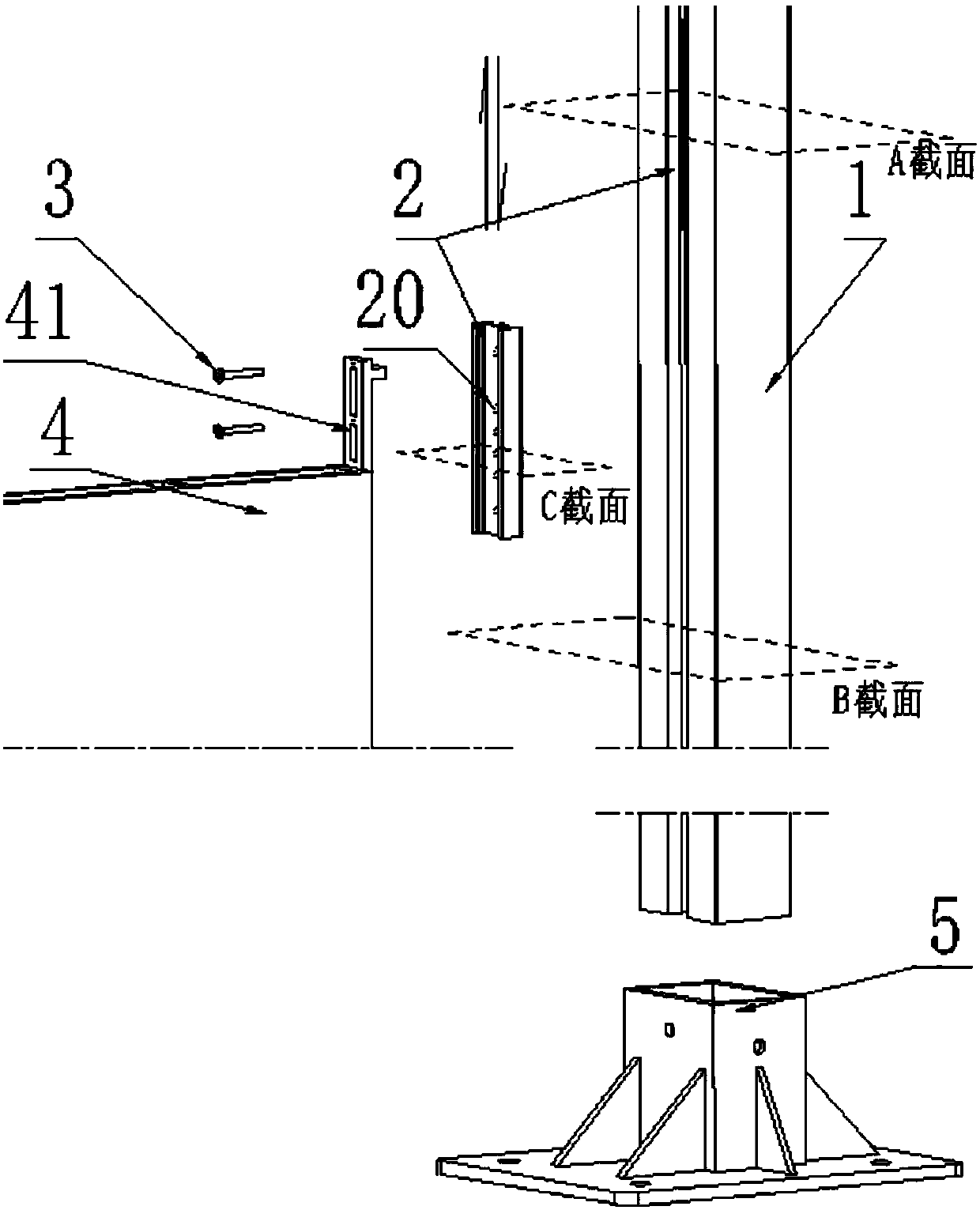
[0064] image 3 Demonstrated access to figure 2 The process drawing of the cross-sectional structure of the rod body shown, it can be seen that, figure 2 The cross-sectional structure shown is composed of four parts, preferably these four parts are assembled together by welding.
[0065] Among them, it includes two "ㄈ"-shaped outer walls 11 with opposite openings, that is, the visible part, with a vertical wall 111 and two cross arms 112, shown as a horizontal "ㄈ" in the figure;
[0066] It also includes two inner walls 12 whose main bodies are rectangular, that is, the invisible part. The middle section of one side of the rectangle is open, and the front ends of the two short walls 123 remaining on the opening side extend vertically to the outside of the rectangle. An extension section 1211 of equal length; the opposite side 1...
Embodiment 2
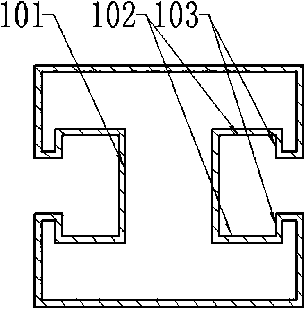
[0084] Such as Figure 5 A cross-section of the body of a stronger mounting rod is shown. Two opposite "concave" shaped outer frames 61 are arranged oppositely, and a rectangular inner frame 62 is spaced and connected between them. The outer frame 61 is the visible part, and the inner frame 62 is the invisible part.
[0085] The width of the "concave" shape notch of the outer frame 61 is longer than the fitting side of the inner frame 62 , but the depth of the notch is shallower than half of the length of the non-fitting side of the inner frame 62 .
[0086] Figure 5 Two grooves are formed inside, the bottom surface 101 of the groove is formed by the non-fitting edge of the inner frame 62, the side surface 102 of the groove is formed by the non-fitting part of the bottom edge of the notch of the outer frame 61, and the standing edge of the notch forms the bottom surface 101 of the notch. The transition surface 103 of the groove. The opposite sides of the two outer frames ...
Embodiment 3
[0106] figure 2 or Figure 5 The outer walls shown are all rectangular, and may actually be designed as polygonal or even arcuate. Any of these shapes will work. However, the grooves are preferably arranged in a plane. At the same time, the bottom surface 101 and / or the side surface 102 of the groove can also be a circular arc surface or a broken line surface, as long as it is compatible with the slider. The material of the mounting rod may be aluminum alloy, steel or engineering plastic.
[0107] For further expansion, multiple grooves can be set on the mounting rod 1, not limited to image 3 or Figure 7 The two shown, at the same time, a plurality of parallel grooves can also be arranged in the same plane.
[0108] The installation rod 1 as a whole can also be formed by connecting multiple parts with the same outline and different cross-sectional structures, and the whole is still an integrated structure. Preferably, when in use, the parts with complex and heavy str...
PUM
 Abstract
Description
Claims
Application Information
 - R&D
- Intellectual Property
- Life Sciences
- Materials
- Tech Scout
- Unparalleled Data Quality
- Higher Quality Content
- 60% Fewer Hallucinations
Browse by: Latest US Patents, China's latest patents, Technical Efficacy Thesaurus, Application Domain, Technology Topic, Popular Technical Reports.
© 2025 PatSnap. All rights reserved.Legal|Privacy policy|Modern Slavery Act Transparency Statement|Sitemap|About US| Contact US: help@patsnap.com


