
Splicing and water entry floating method for ship lift chamber of ship lift for hydropower station

A technology for ship-bearing compartments and hydropower stations, which is applied in the vertical lifting of ship machinery, ship lifting devices, buildings, etc. It can solve problems such as difficult splicing and installation, difficult lifting and installation, and inability to transport super-large components, so as to improve assembly accuracy and welding quality , to ensure reliable operation and accurate positioning

Inactive Publication Date: 2018-03-06
GUIZHOU WUJIANG HYDROPOWER DEV
View PDF2 Cites 2 Cited by
  • Summary
  • Abstract
  • Description
  • Claims
  • Application Information

AI Technical Summary

Problems solved by technology

Due to the requirements of mechanical and balance performance, the manufacturing precision of such components is high, and usually needs to be manufactured and formed in the factory. However, the super-large components after forming can hardly be transported with the existing means of transportation and conditions, even if they are transported to the construction site. It is difficult to lift and install, so it can only be dismantled and assembled at the construction site. Limited by the facility conditions at the construction site, under the normal operating conditions of the reservoir, when the first-stage ship lift does not have the ability to drain the cabin room on the ship When the compartment is manufactured, it is also difficult to splice and install on site at this time

Method used


Image

  • Splicing and water entry floating method for ship lift chamber of ship lift for hydropower station
  • Splicing and water entry floating method for ship lift chamber of ship lift for hydropower station
  • Splicing and water entry floating method for ship lift chamber of ship lift for hydropower station

Examples


Embodiment Construction

[0021] In order to make the object, technical solution and advantages of the present invention clearer, the present invention will be further described in detail below in conjunction with the accompanying drawings.

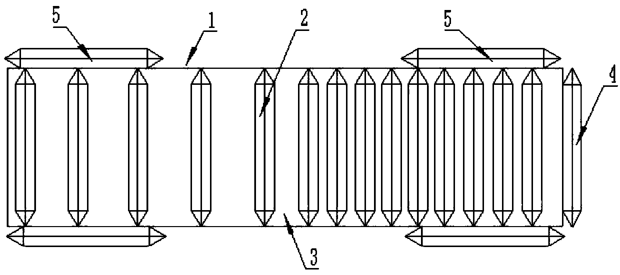
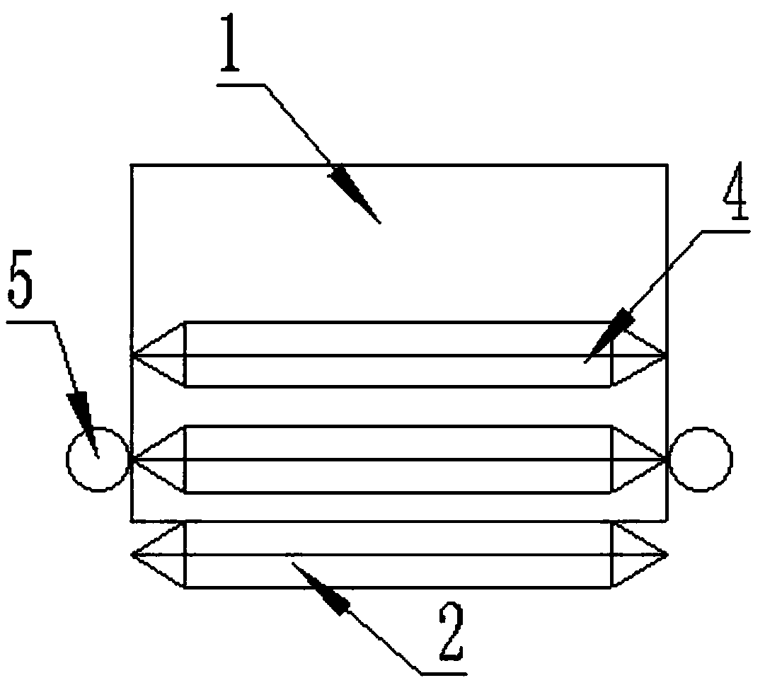
[0022] refer to Figure 1 to Figure 4 According to an embodiment of the present invention, a method for splicing a ship-bearing compartment of a ship lift of a hydropower station into the water for floating transportation comprises the following steps:

[0023] Step 1: Complete the manufacture of each component of the ship-holding compartment 1 at the manufacturer;

[0024] Step 2: Set up an assembly yard for the ship's container 1 in the reservoir area of ​​the hydropower station, and set up an assembly platform whose scale should meet the requirements for the assembly of the ship's container structure, and the launching platform should be close to the waterway, or easily reach the waterway;

[0025] Step 3: Transport the components of the ship-bearing compartme...


PUM


Abstract

The invention discloses a splicing and water entry floating method for a ship lift chamber of a ship lift for a hydropower station. The method comprises the following steps: 1: completing the manufacture of parts of a ship lift chamber in a manufacturer; 2: setting up a ship lift chamber assembly yard in a reservoir area of the hydropower station, and setting up an assembly platform of which the scale should be sufficient to meet the requirements of a ship chamber structure assembly, and a water entry platform being close to a waterway, or easy to reach the waterway; 3: transporting the partsof the ship lift chamber from the manufacture to an assembly platform in the reservoir area of the hydropower station to be assembled; 4: floating the spliced ship lift chamber to the ship chamber inan airbag water entry way, wherein during water entry and floating, the water level of the reservoir is controlled to be more than the sum of the height of lock head on a first level of ship lift andthe draft of the whole ship lift chamber during floating. Compared with ship chamber splicing assembly, the splicing and water entry floating method provided by the invention has the advantages of effectively reducing production cost, keeping the water level running at a high water level, and increasing the economic benefits.

Description

technical field [0001] The invention relates to a method for splicing a ship-bearing compartment of a ship lift of a hydropower station into the water for floating transportation, and belongs to the technical field of installation of a hydro-generator ship-bearing compartment. Background technique [0002] The ship-carrying box of the ship lift used to build the dam of the hydropower station is a super-large steel component, which is composed of main longitudinal beams arranged on both sides in the longitudinal direction and bottom plates connecting the main longitudinal beams on both sides. Due to the requirements of mechanical and balance performance, the manufacturing precision of such components is high, and usually needs to be manufactured and formed in the factory. However, the super-large components after forming can hardly be transported with the existing means of transportation and conditions, even if they are transported to the construction site. It is difficult to...

Claims


Application Information

Patent Timeline
Patent Type & Authority Applications(China)
IPC IPC(8): E02C5/02
CPCE02C5/02
Inventor 杨焱王贵来宋金育易吉林吴让林马要坡
Owner GUIZHOU WUJIANG HYDROPOWER DEV
Learn More