Drainage pipe system

A technology of drainage pipes and pipe bodies, applied in drainage, safety devices, mining equipment, etc., can solve the problems of long operation time and inability to drain in time, achieve high pressure resistance, improve the effect of centralized drainage, and the effect of large expansion coefficient

Inactive Publication Date: 2018-03-06
朱丹
View PDF1 Cites 0 Cited by
  • Summary
  • Abstract
  • Description
  • Claims
  • Application Information

AI Technical Summary

Problems solved by technology

[0003] Although this disclosed drainage pipe has a certain effect on preventing water seepage, it is the same as the traditional ce

Method used


Image

  • Drainage pipe system
  • Drainage pipe system

Examples


Embodiment 1

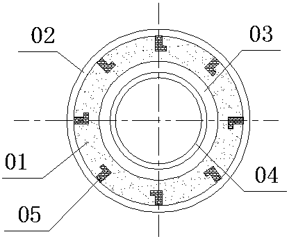
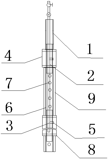
[0027] like figure 2 As shown, the drainage pipe system includes an expansion part and a seepage part, wherein the expansion part includes at least one section of pipe body I1 made of seamless steel pipe, and the outside of the pipe body I1 is wrapped with an annular hollow inflatable air bag 4. The main ventilation pipe 2 made of seam steel pipe is placed in the pipe body I1, and the main ventilation pipe 2 is provided with ventilation holes 3 equal in number to the annular hollow inflatable airbag 4, and the annular hollow inflatable airbag 4 The ventilation pipe 5 communicates with the ventilation hole 3 of the main ventilation pipe 2 through the pipe body I1, and the water seepage part includes at least one pipe body II6 made of seamless steel pipe, and the pipe body I1 is separated from the pipe body II6 It is set and communicated, and at least one drain hole 7 is set on the pipe body II6, and one end of the drain pipe is inserted into the surrounding rock for sealing. ...

Embodiment 2

[0030] like figure 2 As shown, on the basis of Example 1, blocking gaskets 8 are provided on both sides of the annular hollow inflatable airbag 2, and the blocking gasket 8 effectively limits the longitudinal deformation of the annular hollow inflatable airbag 2, and enhances the airbag's impact on the surrounding area. The radial extrusion of the rock is more conducive to the rapid fixation of the drainpipe.

Embodiment 3

[0032] like figure 2 As shown, on the basis of Example 1, the pipe body II6 is wrapped with non-woven fabric 9, and the non-woven fabric 9 provides a good drainage channel for the seepage of surrounding rock, so that the drainage pipe can drain water more effectively.


PUM

PropertyMeasurementUnit
Diameteraaaaaaaaaa
Diameteraaaaaaaaaa

Abstract

The invention discloses a drainage pipe system, comprising an expansion part and a water seepage part, wherein the expansion part comprises at least one pipe body I (1) and an annular hollow expansion air bag (4) wrapped around the outside of the pipe body I (1). . The main ventilation pipe (2) placed in the pipe body I (1), the seepage part includes at least one pipe body II (6), and the pipe body I (1) and the pipe body II (6) are arranged at intervals In parallel connection, at least one drain hole (7) is provided on the pipe body II (6), and one end port of the drain pipe inserted into the surrounding rock is sealed. By inflating the airbag, the drainage pipe can be quickly fixed in the surrounding rock, so that the surrounding rock can be drained in a concentrated manner. When no drainage is needed, deflate and contract through the airbag, take out the drain, and reuse it.

Description

technical field [0001] The invention relates to the field of drainage pipes for tunnel construction, in particular to a drainage pipe system. Background technique [0002] In the construction of highways, railways, subways and other projects, tunnel excavation is an inevitable and extremely important part, and drainage in tunnels is also very important. Once water leakage occurs, it will not only affect the construction, but also easily cause safety accidents. Traditional tunnel drainage mostly lays cement drainage pipes in the surrounding rock, which is prone to water leakage and is not safe. Chinese patent CN202946194U discloses a figure 1 The drainage pipe system shown is an improvement on the traditional cement drainage pipe, and its technical solution is: a drainage pipe system, which includes a cement pipe 01 with a circular cross section, and a metal protective plate 02 is arranged on the outer wall of the cement pipe , the outer wall of the metal protective plate i...

Claims


Application Information

Patent Timeline
IPC IPC(8): E21F16/02
CPCE21F16/02
Inventor 朱丹
Owner 朱丹
Why Eureka
Try Eureka