
Clutch hydraulic control system for double-planet-row confluence hydro-mechanical continuously variable transmission

A technology of hydraulic control system and continuously variable transmission, which is applied to the control of clutches, mechanical equipment, and transmission devices. The effect of stability, compact structure and easy mass production

Inactive Publication Date: 2018-03-06
NANJING AGRICULTURAL UNIVERSITY
View PDF4 Cites 9 Cited by
  • Summary
  • Abstract
  • Description
  • Claims
  • Application Information

AI Technical Summary

Problems solved by technology

When the vehicle is running, the hydraulic continuously variable transmission makes feedback changes with the road surface conditions and workload, which reduces the impact of the clutch during the gear shifting process of the vehicle, increases the working life of the clutch, improves the stability of the vehicle during work and the comfort of the driver. The overall service life of the vehicle has been improved, but the existing hydraulic continuously variable transmission has a large overall structure, low space utilization, and is prone to oil leakage problems. The structure and performance still need to be improved and improved
[0005] Furthermore, the HMCVT transmission method adopts the hydraulic continuously variable transmission power and the mechanical stepped transmission power to converge in the planetary row. In order to increase the working efficiency and transmission ratio range of the transmission, the HMCVT usually uses multiple clutches and planetary row structures to realize the multi-stage continuously variable transmission mechanism. , in the transmission of each clutch, it is necessary to control the transmission ratio of the variable pump-quantitative motor, and to control the coupling and separation of the clutch. If the above functions are manually controlled, it will cause difficulties for the driver to operate.

Method used


Image

  • Clutch hydraulic control system for double-planet-row confluence hydro-mechanical continuously variable transmission
  • Clutch hydraulic control system for double-planet-row confluence hydro-mechanical continuously variable transmission
  • Clutch hydraulic control system for double-planet-row confluence hydro-mechanical continuously variable transmission

Examples


Embodiment Construction

[0023] The present invention will be further described below in conjunction with the accompanying drawings. The following examples are only used to illustrate the technical solution of the present invention more clearly, but not to limit the protection scope of the present invention.

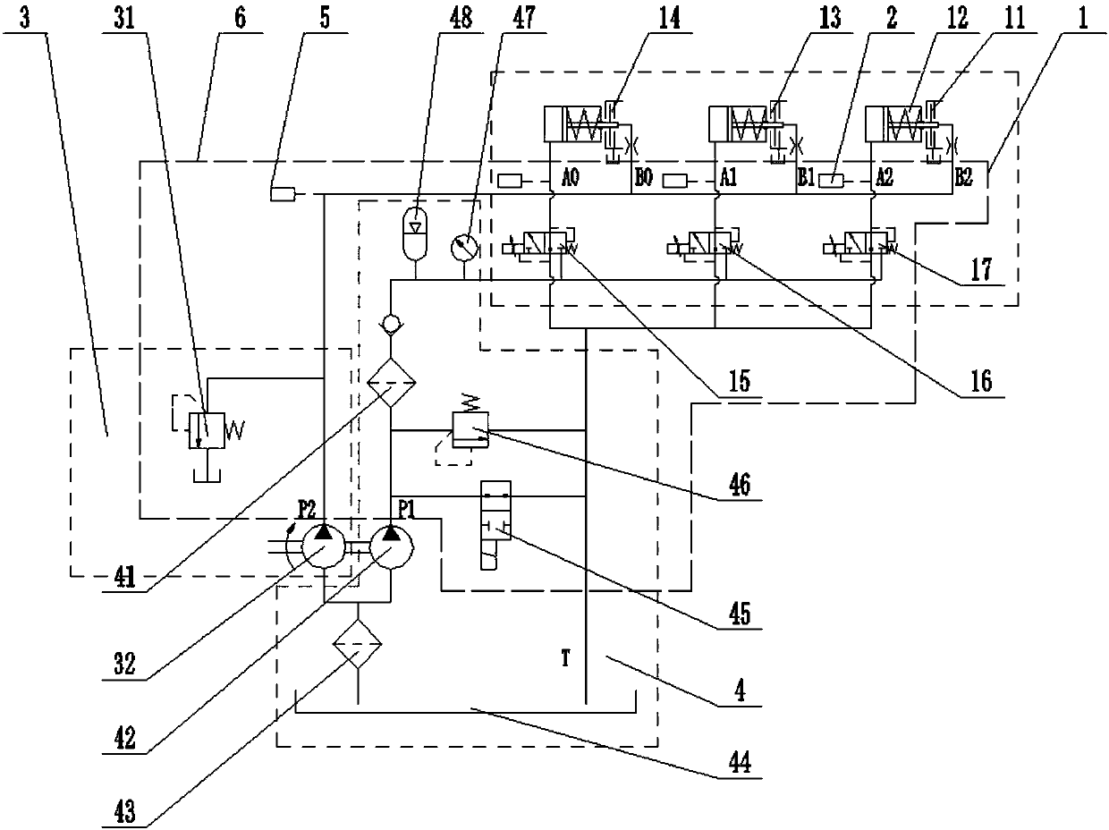
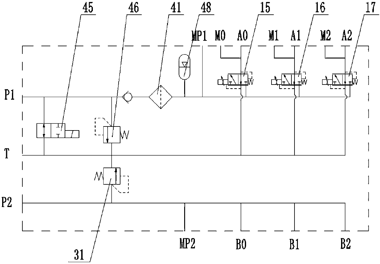
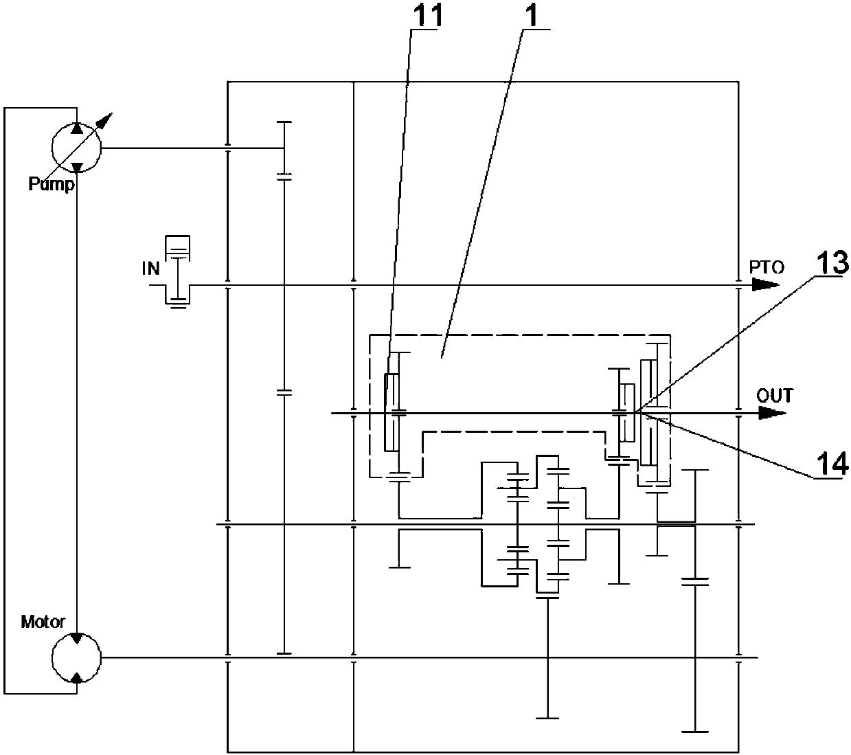
[0024] Such as figure 1 with image 3 As shown, a clutch hydraulic control system of a dual-planetary confluence hydraulic-mechanical continuously variable transmission includes a shift mechanism clutch control system 1 , a lubricating cooling system 3 and an oil supply system 4 . The oil supply system 4 supplies oil to the shift mechanism clutch control system 1 and the shift mechanism clutch lubrication and cooling system 3 . The shift mechanism clutch control system 1 includes a third hydraulic clutch 11, a spring return oil cylinder 12, a second hydraulic clutch 13, a first hydraulic clutch 14, a first proportional pressure reducing valve 15, a second proportional pressure reducing valve 16...


PUM


Abstract

The invention discloses a clutch hydraulic control system for a double-planet-row confluence hydro-mechanical continuously variable transmission. The clutch hydraulic control system comprises a clutchcontrol system, a lubricating cooling system and an oil supply system. The oil supply system comprises an oil tank. Oil in the oil tank passes through a rough filter and then passes through a low-pressure large-flow gear pump and a high-pressure small-flow gear pump after. The low-pressure large-flow gear pump communicates with a first hydraulic clutch, a second hydraulic clutch and a third hydraulic clutch. An oil outlet of the high-pressure small-flow gear pump communicates with a precise filter, and the precise filter communicates with a first proportional pressure reducing valve, a secondproportional pressure reducing valve and a third proportional pressure reducing valve. The three proportional pressure reducing valves communicate with spring reset oil cylinders. The three hydraulicclutches are connected into a control oil way through the three spring reset oil cylinders. By means of the clutch hydraulic control system for the double-planet-row confluence hydro-mechanical continuously variable transmission, the structure is simpler, the size is reduced, the cost is reduced, the oil pressure is stably controlled, hydraulic oil compensation can be conducted on oil leakage ofthe system, and reliability of the lubricating cooling system is high.

Description

technical field [0001] The invention relates to a clutch hydraulic control system of a dual-planetary confluence hydraulic-mechanical continuously variable transmission, and belongs to the technical field of clutch control of hydraulic-mechanical continuously variable transmissions. Background technique [0002] When agricultural, engineering and military machinery vehicles are working, the transmission power is large, the speed range is wide, and the operating conditions are complex. Traditional vehicle power mostly uses multi-speed stepped gear transmissions. Drivers need to frequently shift gears when the vehicle is working to meet Vehicle power, economy and other requirements, work intensity is high, production efficiency is low, and the vehicle cannot be guaranteed to be in the best working condition. [0003] In addition, the traditional multi-speed stepped gear transmission cannot realize continuous speed change. The structure of the transmission is complex, the manuf...

Claims


Application Information

Patent Timeline
IPC IPC(8): F16H61/00F16D48/02
CPCF16H61/0025F16D48/0206F16D2048/0203F16D2048/0221F16D2048/0236F16D2048/0263F16D2048/029F16H61/0009F16H2061/0034F16H2061/0037
Inventor 钱进史立新肖茂华张海军鲁植雄
Owner NANJING AGRICULTURAL UNIVERSITY
Learn More