
Novel pressure stabilization overflow valve

An overflow valve and voltage stabilization technology, applied in the field of hydraulic control, can solve the problems of pressure fluctuations at the back end of the voltage stabilization device, complex structure, and large space occupation, so as to improve shift performance, overcome complex structure, and small pressure drop Effect

Active Publication Date: 2017-01-04
XIAN FLIGHT SELF CONTROL INST OF AVIC
View PDF8 Cites 1 Cited by
  • Summary
  • Abstract
  • Description
  • Claims
  • Application Information

AI Technical Summary

Problems solved by technology

[0003] The technical problem to be solved by the present invention is to solve the problem that the pressure stabilizing device in the automatic transmission hydraulic control system is affected by the back-end pressure fluctuation and its structure is complex and occupies a large space

Method used


Image

  • Novel pressure stabilization overflow valve

Examples


Embodiment Construction

[0010] The working principles and embodiments of the present invention will be described in detail below in conjunction with the attached structural diagrams, but the details of the structural diagrams and embodiments are not intended to limit the present invention, and any use of the working principles of the present invention should belong to the protection scope of the present invention.

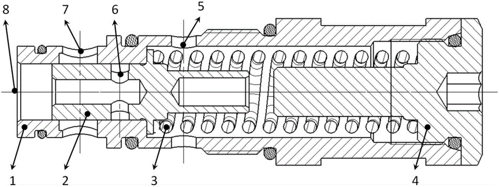
[0011] figure 1 The structure diagram of the pressure-stabilizing relief valve mainly used in the hydraulic control system of automatic transmission provided by the present invention is composed of valve sleeve 1, spool 2, spring 3, and limit plug 4. The spool 2 has a limit convex After being installed in the valve sleeve 1, it can only move in one direction (the opening direction of the valve port). The centering structure of the spring 3 is arranged on the valve core 2 and the limit plug 4, and a limit rod is designed on the limit plug 4 to limit the maximum stroke of the valve core and...


PUM


Abstract

The invention belongs to a hydraulic control technology, and particularly relates to a pressure stabilization overflow valve for a hydraulic control system of an automatic transmission. At present, the pressure stabilization function is achieved mainly through cooperation of multiple function valves, the overflow valve is liable to be affected by pressure fluctuation, the structure is complex, and the occupied mounting space is relatively large. The novel pressure stabilization overflow valve comprises a valve sleeve, a valve core, springs, a limiting plug, an oil return hole, a working hole and an oil inlet, wherein the limiting plug is in threaded connection with one opening end of the valve sleeve; the oil inlet is in the other end of the valve sleeve; the valve core is a cylindrical slide valve; the valve core has an annular bulge on the outer side; an axial oil hole and a radial overflow hole which communicates with the axial oil hole are formed in the side, near the oil inlet, of the valve core; and the limiting plug presses the valve core on the step surface of an inner hole of the valve sleeve through the springs. According to the novel pressure stabilization overflow valve, the problems that a pressure stabilization device in the hydraulic control system of the automatic transmission is affected by pressure fluctuation at the back end, the structure is complex, and the occupied mounting space is relatively large are solved.

Description

technical field [0001] The invention belongs to hydraulic control technology, in particular to a pressure stabilizing overflow valve used in a hydraulic control system of an automatic transmission. Background technique [0002] In the automatic transmission hydraulic control system, a constant pressure before the clutch control valve is realized through a pressure stabilizing device, and a large flow is distributed for the operation of the hydraulic torque converter at the same time. Since the pressure drop produced by the hydraulic torque converter is different at different flow rates and temperatures, it is necessary for the pressure stabilizing device to pass a large flow rate and keep the pressure before the valve from being affected by fluctuations at the rear end. At present, the voltage stabilization function is mainly realized through the combination of several functional valves, which is easily affected by pressure fluctuations, and has a complex structure and takes...

Claims


Application Information

Patent Timeline
Patent Type & Authority Applications(China)
IPC IPC(8): F16K17/30F16H61/00
CPCF16H61/0009F16K17/30
Inventor 赵锋花韬陈小磊田一松苏安萍
Owner XIAN FLIGHT SELF CONTROL INST OF AVIC
Learn More