Exhaust device, refrigerating air-conditioning unit and non-condensable gas exhaust method

A technology for exhaust devices and air-conditioning units, which is applied in the direction of refrigerators, refrigeration components, refrigeration and liquefaction, etc., and can solve problems such as the decline in heat transfer performance of the condenser, the increase in the exhaust temperature of the compressor, and the stuck compressor, etc., to achieve Guaranteed cooling capacity and energy efficiency, and the effect of maintaining condensing pressure

Inactive Publication Date: 2018-03-06
YORK WUXI AIR CONDITIONING & REFRIGERATION CO LTD +1
View PDF3 Cites 10 Cited by
  • Summary
  • Abstract
  • Description
  • Claims
  • Application Information

AI Technical Summary

Problems solved by technology

Due to the existence of the low-pressure area, air may infiltrate into the interior of the refrigeration and air-conditioning unit, causing non-condensable gas to accumulate in the condenser, resulting in a decrease in the heat transfer performance of the condenser, thereby reducing the cooling capacity of the refrigeration and air-conditioning unit; at the same time, the condensing pressure of the system increases High, the condensing temperature rises, which further leads to an increase in the discharge temperature of the compressor, an increase in power consumption, and a decrease in the energy efficiency of the refrigeration and air conditioning unit
In addition, due to the high exhaust temperature, the lubricating oil of the compressor may be carbonized, affecting the lubrication effect. In severe cases, the compressor may be stuck or the compressor motor may be burned.

Method used


Image

  • Exhaust device, refrigerating air-conditioning unit and non-condensable gas exhaust method
  • Exhaust device, refrigerating air-conditioning unit and non-condensable gas exhaust method
  • Exhaust device, refrigerating air-conditioning unit and non-condensable gas exhaust method

Examples


Embodiment Construction

[0043] In the following description, a lot of specific details are given in order to provide a more thorough understanding of the present invention. However, it is obvious to those skilled in the art that the present invention can be implemented without one or more of these details. In other examples, in order to avoid confusion with the present invention, some technical features known in the art are not described.

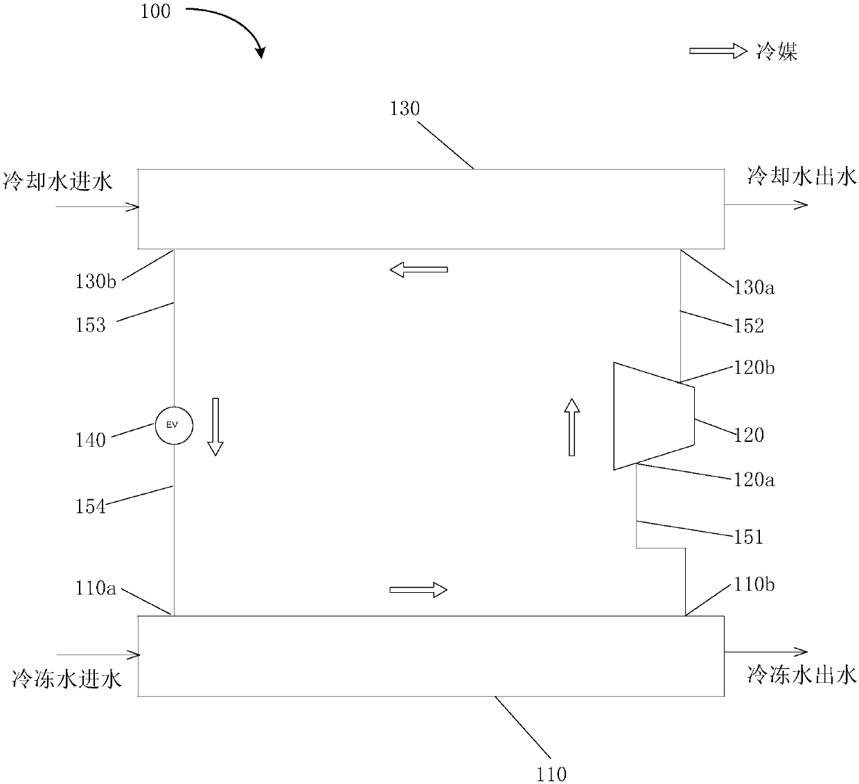
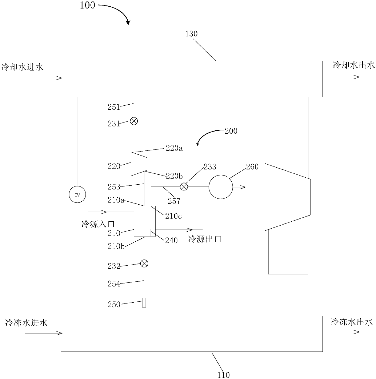
[0044] The invention is mainly applied to refrigeration and air-conditioning units using low-pressure refrigerants (such as R123, R1233zd, etc.).

[0045] Specifically, the system structure of the refrigeration and air conditioning unit 100 is composed as figure 1 As shown, it mainly includes four main parts: the evaporator 110, the first compressor 120, the condenser 130, and the throttle valve 140. These four parts are in fluid communication with the external environment and form a closed system with respect to the external environment. The closed system of the refr...


PUM


Abstract

The invention provides an exhaust device, a refrigerating air-conditioning unit and a non-condensable gas exhaust method. The exhaust device comprises an exhaust compressor and a heat exchanger, wherein a gas suction opening of the exhaust compressor is connected with a condenser of the refrigerating air-conditioning unit, so that a mixed gas consisting of a gaseous refrigerant and a non-condensable gas is introduced into the exhaust compressor by the condenser to be compressed; a gas inlet of the heat exchanger is connected with an exhaust opening of the exhaust compressor; a liquid outlet ofthe heat exchanger is connected with an evaporator or the condenser of the refrigerating air-conditioning unit; the heat exchanger is provided with a cold source inlet and a cold source outlet whichallow a cold source to flow; the compressed mixed gas enters the heat exchanger to exchange heat with the cold source, a gaseous refrigerant is condensed into a liquid refrigerant which is then discharged into the evaporator or the condenser, and a gas outlet allows the separated non-condensable gas to be discharged out of the heat exchanger. According to the exhaust device, the non-condensable gas in the refrigerating air-conditioning unit can be effectively separated and discharged, so that safe and efficient running of the exhaust device is guaranteed.

Description

Technical field [0001] The present invention generally relates to the field of air conditioning and refrigeration, and more specifically to an exhaust device, a refrigeration and air conditioning unit and a method for exhausting non-condensable gas. Background technique [0002] The traditional refrigeration and air-conditioning unit consists of four major components: compressor, condenser, throttle and evaporator. For some refrigeration and air-conditioning units that use low-pressure refrigerants (such as R123, R1233zd, etc.), during operation, the system of the refrigeration and air-conditioning unit will form some low-pressure areas below atmospheric pressure. Due to the existence of the low pressure zone, air may penetrate into the refrigeration and air-conditioning unit, causing non-condensable gas to accumulate in the condenser, resulting in a decrease in the heat exchange performance of the condenser, thereby reducing the cooling capacity of the refrigeration and air-cond...

Claims


Application Information

Patent Timeline
Patent Type & Authority Applications(China)
IPC IPC(8): F25B43/04F25B49/02
CPCF25B43/043F25B43/003F25B49/02F25B2500/06F25B2500/09
Inventor 王生龙薛芳苏秀平
Owner YORK WUXI AIR CONDITIONING & REFRIGERATION CO LTD
Why Eureka
Try Eureka