
Electrical resistivity correcting method for mine transient electromagnetic method

A technology of transient electromagnetic method and correction method, which is applied in electric/magnetic exploration, radio wave measurement systems, instruments, etc. The effect of eliminating mutual inductance signals and solving the problem of low resistivity distortion

Active Publication Date: 2018-03-06
CHINA UNIV OF MINING & TECH (BEIJING) +1
View PDF7 Cites 10 Cited by
  • Summary
  • Abstract
  • Description
  • Claims
  • Application Information

AI Technical Summary

Problems solved by technology

[0004] Aiming at the deficiencies in the above-mentioned prior art, the present invention provides a mine transient electromagnetic method resistivity correction method to solve the problem of mine transient electromagnetic method low resistivity distortion

Method used


Image

  • Electrical resistivity correcting method for mine transient electromagnetic method
  • Electrical resistivity correcting method for mine transient electromagnetic method
  • Electrical resistivity correcting method for mine transient electromagnetic method

Examples


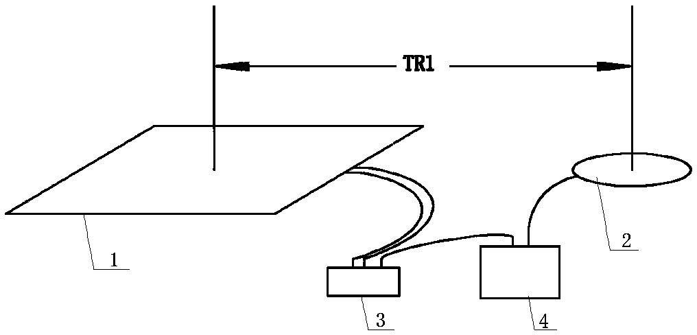
Embodiment 1

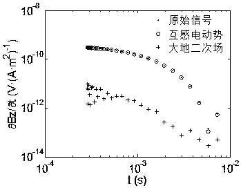
[0025] In order to illustrate the resistivity correction effect of the method of the present invention, the comparative test results of the conventional method and the method of the present invention are given.

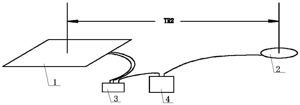
[0026] Conventional method and detection test of the method of the present invention are all carried out in certain mine roadway. The geological conditions of the detection site are known. According to geological and drilling data, there are no abnormal structures and water-bearing bodies within the detection range, and the average resistivity of the formation is 80Ω·m. The detection instrument adopts the same type of transient electromagnetic instrument, 1.5m×1.5m×81-turn transmitting coil, 25Hz system frequency, and 30 sampling time gates (6.8μs~6978μs equilogarithmic division).

[0027] The specific steps of the conventional method are:

[0028] (1) Place the transmitting coil 1 at the measuring point, set the transmitting and receiving distance as TR1=8m, and obt...


PUM


Abstract

The invention relates to an electrical resistivity correcting method for a mine transient electromagnetic method. The method includes 1, placing an emitting coil at a measurement point position, setting a transmit-receive distance as TR1, acquiring a primary field value as indicated in the description and a secondary field value containing mutual inductance electro-dynamic potential as indicated in the description through instrument data collection; 2, keeping the position of the emitting coil unchanged, increasing the transmit-receive distance to TR2, acquiring primary field value as indicated in the description and a secondary field value containing mutual inductance electro-dynamic potential as indicated in the description through instrument data collection; 3, putting collected data into a correction formula as indicated in the description for cancelling the mutual inductance electro-dynamic potential, and obtaining a ground secondary field signal V2; 4, performing whole-area apparent resistivity calculation and time depth conversion on the secondary field signal V2 subjected to mutual inductance electro-dynamic potential cancelling and obtaining an apparent resistivity-depth curve. According to the invention, electrical resistivity correction is performed by utilizing transmit-receive distance observation data of two different processes and mutual inductance signals are cancelled, the valid ground secondary field signal is extracted and a problem of electric resistivity distortion caused by using the mine transient electromagnetic method can be solved well. Since the detection depth is in direct proportion to and the electric resistivity, the detection depth of the mine transient electromagnetic method is improved.

Description

technical field [0001] The invention relates to the field of geology and exploration geophysics, in particular to a mine transient electromagnetic resistivity correction method. Background technique [0002] Transient Electromagnetic Method (TEM) is a time-domain artificial source electromagnetic detection method based on the principle of electromagnetic induction. It is a geophysical method that uses ungrounded return wires or grounding wires to launch a primary field underground, and after the primary field is turned off, measures the secondary field induced by the underground medium over time to find various geological targets. Exploration methods. When the transient electromagnetic method is applied to underground mine detection, it is called Mine Transient Electromagnetic Method (MTEM for short). [0003] The mine transient electromagnetic method uses a multi-turn square (or circular) small loop source with a side length of less than 2m for detection. Due to the limit...

Claims


Application Information

Patent Timeline
Patent Type & Authority Applications(China)
IPC IPC(8): G01V3/38G01V3/08
CPCG01V3/08G01V3/38
Inventor 程久龙李飞温来福张洪川张睿敏
Owner CHINA UNIV OF MINING & TECH (BEIJING)
Learn More