Multi-functional base-based live-line operation unmanned aerial vehicle for power transmission line
A technology for transmission lines and live work, applied in the direction of overhead lines/cable equipment, etc., can solve the problems of increased cost and inconvenient transportation, and achieve the effects of uniform pressure, strong practicability, and improved stability
- Summary
- Abstract
- Description
- Claims
- Application Information
AI Technical Summary
Problems solved by technology
Method used
Image
Examples
Embodiment 1
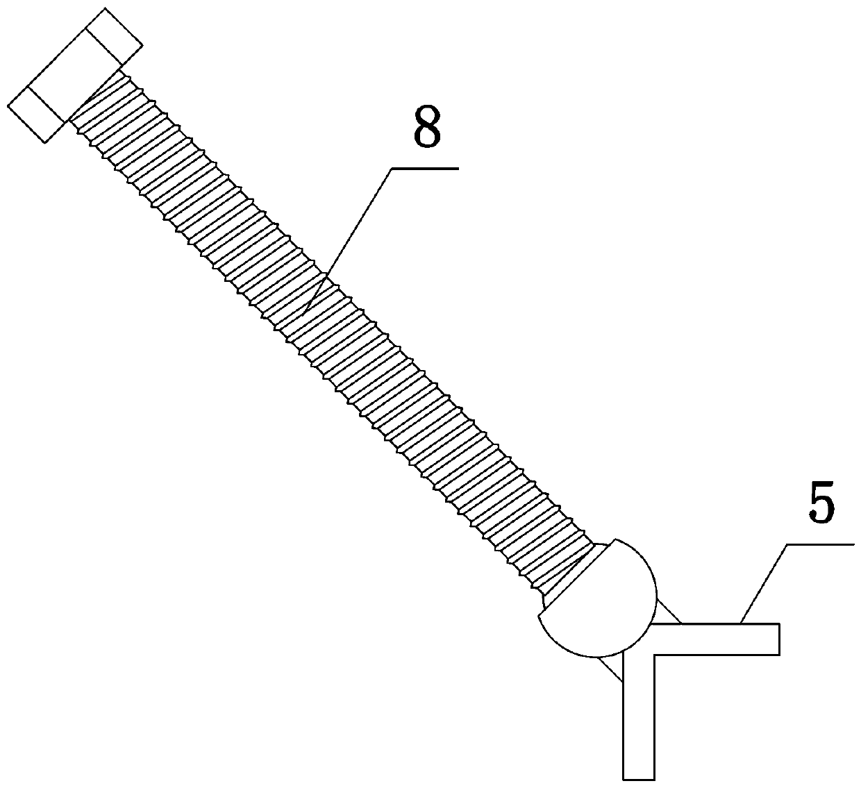
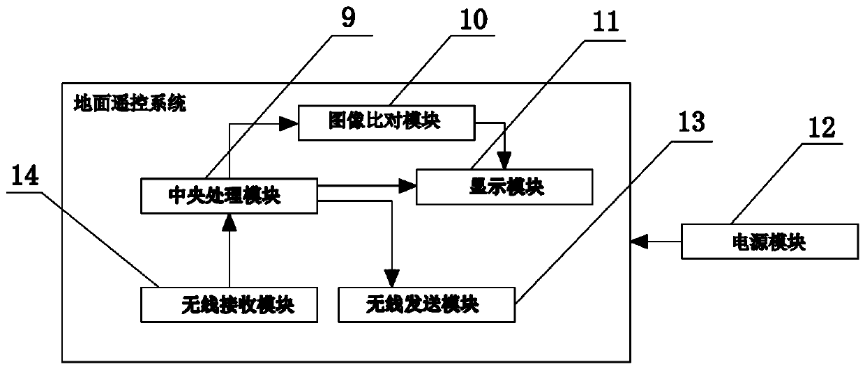
[0033] Such as figure 1 with figure 2 As shown, the present invention includes a wireless communication aerial operation system and a ground remote control system. The aerial operation system includes an unmanned aerial vehicle 1 and an elevating support 2 arranged at the lower end of the unmanned aerial vehicle 1. The elevating support 2 is provided with a bearing base, which includes four A side baffle 3, a bottom plate 4 and four pressure plates 5, the side baffle 3 and the bottom plate 4 are buckled and fixed with the lifting bracket 2 respectively, the pressure plate 5 is an L-shaped structure, and the four side baffles 3 and the base plate 4 form a circle. In the accommodating cavity, two support arms 6 are arranged on the upper end of each side baffle 3, and a rotating shaft 7 is arranged between the two support arms 6, and a threaded through hole is arranged on the rotating shaft 7, and the central axis of the rotating shaft 7 and the side baffle 3 The extension dire...
Embodiment 2
[0036] Such as figure 1 with figure 2As shown, the aerial work system of the present invention includes an unmanned aerial vehicle 1 and an elevating support 2 arranged at the lower end of the unmanned aerial vehicle 1. The elevating support 2 is provided with a bearing base, and the bearing base includes four side baffles 3, a base plate 4 and four A pressing plate 5, the side baffles 3 and the base plate 4 are buckled and fixed with the lifting bracket 2 respectively, the pressing plate 5 is an L-shaped structure, and the four side baffles 3 and the base plate 4 form a receiving cavity, and the upper end of each side baffle 3 Two support arms 6 are both arranged, and a rotating shaft 7 is arranged to rotate between the two supporting arms 6. A threaded through hole is arranged on the rotating shaft 7. The central axis of the rotating shaft 7 is parallel to the extension direction of the side baffle plate 3, and the central axis of the threaded through hole The central axis...
Embodiment 3
[0039] The structure of this embodiment is basically the same as that of Embodiment 1, the difference is: as Figure 5 As shown, a plurality of grooves 17 are arranged on the edge of the lower end surface of the bottom plate 4, and the grooves 17 are arc-shaped.
PUM
 Abstract
Description
Claims
Application Information
 - R&D
- Intellectual Property
- Life Sciences
- Materials
- Tech Scout
- Unparalleled Data Quality
- Higher Quality Content
- 60% Fewer Hallucinations
Browse by: Latest US Patents, China's latest patents, Technical Efficacy Thesaurus, Application Domain, Technology Topic, Popular Technical Reports.
© 2025 PatSnap. All rights reserved.Legal|Privacy policy|Modern Slavery Act Transparency Statement|Sitemap|About US| Contact US: help@patsnap.com


