Automatic assembling equipment for optical fiber connector

An optical fiber connector, automatic assembly technology, applied in metal processing equipment, assembly machines, manufacturing tools and other directions, can solve the problems of low manual assembly efficiency, high connection reliability, low quality, etc., to achieve compact structure, improve assembly efficiency, The effect of shortening the workflow

Inactive Publication Date: 2018-03-09
XUCHANG UNIV
View PDF6 Cites 18 Cited by
  • Summary
  • Abstract
  • Description
  • Claims
  • Application Information

AI Technical Summary

Problems solved by technology

[0003] Optical fiber connectors generally include six parts: plastic parts, springs, optical fiber cores, guide tubes, housing parts and dust caps. The components are small in size, and the connection reliability between the components is high. When manually assembling the optical fiber connector, it takes more time to pick up the components, align the components, and install the components. The efficiency of manual assembly is low, the cost is high, and the quality is low.

Method used


Image

  • Automatic assembling equipment for optical fiber connector
  • Automatic assembling equipment for optical fiber connector
  • Automatic assembling equipment for optical fiber connector

Examples


Embodiment 1

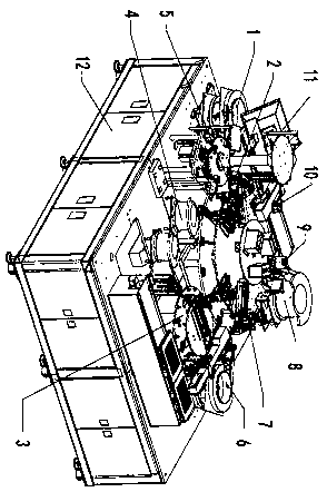
[0037] like figure 1 Shown, an embodiment 1 of the present invention is:

[0038] An automatic assembly equipment for optical fiber connectors, including a frame 12, three rotating disks are arranged on the left side of the top plate of the It is used to fix the second rotating disk of each clamping mechanism and the third rotating disk for arranging a plurality of first positioning seats. The lower part of the frame 12 is provided with an electric control system and an air storage tank for providing air pressure; the frame The right side of the top plate of 12 is provided with an optical fiber plug mechanism 3 for providing an optical fiber core and a guide tube assembly, and a plastic part feeding mechanism 1 and a spring feeding mechanism 4 are sequentially arranged on the top plate of the frame 12 along the rotation direction of the rotating disk , shell parts feeding mechanism 6, fastening sleeve feeding mechanism, dust cap feeding mechanism 8 and finished product receiv...

Embodiment 2

[0040] Embodiment 2: The lower end of the human-computer interaction display screen 11 is equipped with a display bracket, and a driven gear is connected to the lower end of the display bracket. One side of the driven gear is provided with a driving gear meshing with it. The shaft device is fixedly connected with the rotating motor, and the driving gear and the driven gear are fixed on the gear bracket.

[0041] The upper wall and the lower wall of the second rotating disk are sequentially provided with the first manipulator 2 for grabbing the plastic parts and placing them on the first positioning seat along the direction of rotation, and the first manipulator 2 for adjusting the position of the plastic parts. Two manipulators 5, a third manipulator 13 for making the spring at the center of the plastic part, a spring detection assembly for detecting whether the spring is placed in the plastic part, for grabbing the optical fiber core and the guiding tube assembly and placing i...

Embodiment 3

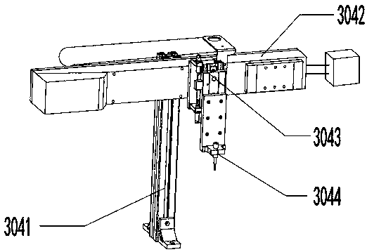
[0045] Embodiment 3: The optical fiber core horizontal assembly 3042 includes a rotating motor, a rolling screw, and a drag chain, and the fixed end of the rotating motor and the fixed end of the drag chain are both fixedly connected to the optical fiber core bracket 3041, so The working end of the rotating motor is fixedly connected to one end of the ball screw through a coupling, and the nut of the ball screw and the movable end of the drag chain are both fixedly connected to the fixed end of the optical fiber core lifting and moving assembly , the optical fiber core lifting and moving assembly moves horizontally driven by the rotating motor.


PUM


Abstract

The invention provides automatic assembling equipment for an optical fiber connector. The automatic assembling equipment for the optical fiber connector comprises a rack, wherein three rotating platesare arranged on the left side of a top plate of the rack; an optical fiber plug mechanism which is used for providing an optical fiber core and a guide tube combined piece is arranged on the right side of the top plate of the rack; and a plastic piece is placed on a positioning seat, then the position of the plastic piece is adjusted, the spring is placed in the center of the plastic piece, whether the optical fiber core and guide tube combined piece is placed on the spring or not is detected, a junction on the optical fiber core and guide tube combined piece is pressed, a shell piece sleevesthe optical fiber core and guide tube combined piece, a fastening sleeve is placed, the shell piece is pressed, the fastening sleeve is taken down, and a dust a is placed on the shell piece. The automatic assembling equipment for the optical fiber connector is compact in structure, the working process is shortened, the assembling efficiency is improved full-automatically, labors are reduced, theassembling precision is improved, a flexible piece is arranged in a material grabbing hand of a manipulator, and thus, parts of optical fiber heads are prevented from being damaged by clamping; and the optical fiber plug mechanism is independent from various manipulators on a second rotating plate, two processes are matched with each other, and the time is saved.

Description

technical field [0001] The invention relates to the technical field of optical fiber device assembly, in particular to automatic assembly equipment for optical fiber connectors. Background technique [0002] Now is the information age, most of them use optical fiber transmission, and there is a great demand for optical fiber connectors; [0003] Optical fiber connectors generally include six parts: plastic parts, springs, optical fiber cores, guide tubes, housing parts and dust caps. The components are small in size, and the connection reliability between the components is high. When manually assembling the optical fiber connector, it takes more time to pick up the components, align the components, and install the components. The efficiency of manual assembly is low, the cost is high, and the quality is low. . Contents of the invention [0004] The present invention provides an automatic assembly device for optical fiber connectors, which solves the above problems. [0...

Claims


Application Information

Patent Timeline
Patent Type & Authority Applications(China)
IPC IPC(8): B23P21/00
CPCB23P21/006
Inventor 杨晓博贾琳
Owner XUCHANG UNIV
Why Eureka
Try Eureka