Composite rotary-cutting mining machine
A mining machine and composite drill bit technology, applied in the direction of slitting machinery, cutting machinery, mining equipment, etc., can solve the problems of wasting power and material resources, increasing production costs, and high resistance, so as to promote the development of mining industry and reduce mining costs , the effect of improving work efficiency
- Summary
- Abstract
- Description
- Claims
- Application Information
AI Technical Summary
Problems solved by technology
Method used
Image

Examples
Embodiment approach 1
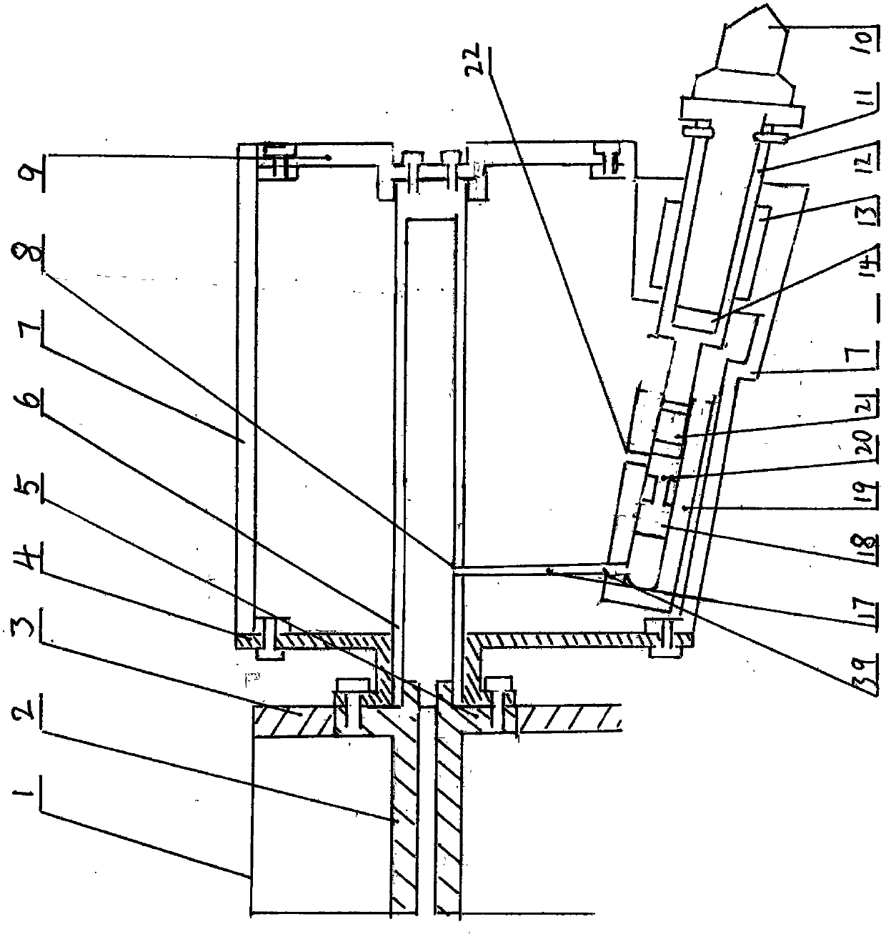
[0053] A compound rotary cutting mining machine, such as figure 1 Shown, the mining machine of the compound rotary cutting of the first embodiment of the present invention, as figure 1 As shown, the mining machine head of the compound rotary cutting of the present invention is the drill bit or the drum 7, the inner side of the mining machine host 1 is provided with a main shaft 2, and the power output shaft end 5 of the main shaft 2 is fixedly connected with the connection plate 4 of the drill bit or the drum 7 Together, the power output shaft end 5 is set in cooperation with the housing 3 of the main engine 1;
[0054] The excavator is provided with an externally connected high-pressure air pipe integrated or arranged inside the main shaft 2;
[0055] The high-pressure air pipe is connected to the drill bit or the drum at the front end of the excavator equipment through the mining machine main shaft 2; The discs 4 are fixedly connected together;
[0056] At least one or mo...
Embodiment approach 2
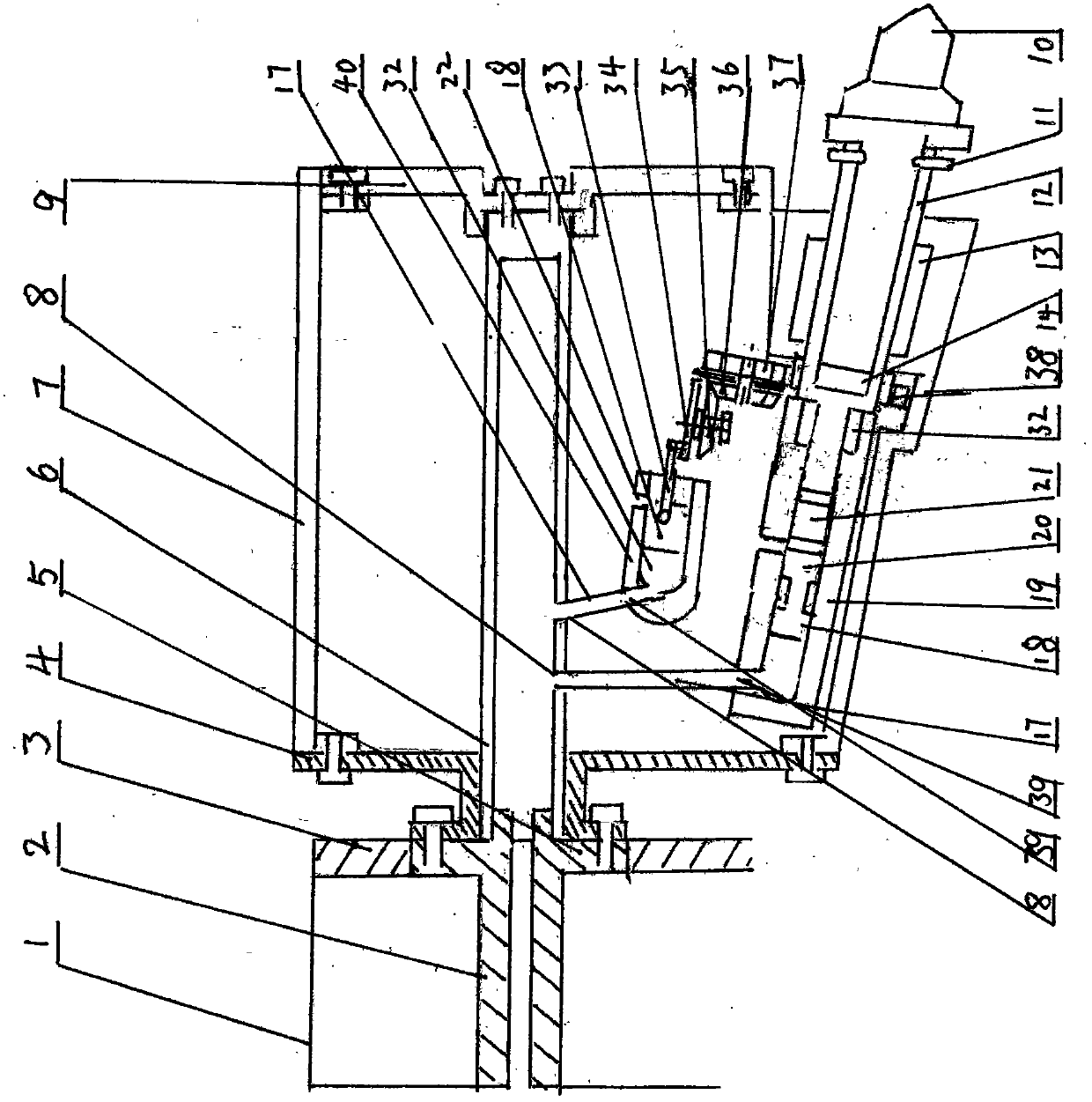
[0065] A compound rotary cutting mining machine, such as figure 2 Shown, the mining machine of the compound rotary cutting of the second embodiment of the present invention, as figure 2 As shown, on the basis of the first embodiment, the mining machine head of the composite rotary cutting of the present invention is a composite drill bit or a composite drum 7, the inside of the mining machine main frame 1 is provided with a main shaft 2, and the power output shaft end 5 of the main shaft 2 It is fixedly connected with the connection plate 4 of the composite drill bit or the composite drum 7, and the power output shaft end 5 is arranged in cooperation with the housing 3 of the main engine 1; the high-pressure air pipe connected externally is provided on the excavator integrally or arranged inside the main shaft 2 ;
[0066] The high-pressure air pipe is connected to the drill bit or the drum at the front end of the excavator equipment through the mining machine main shaft 2;...
Embodiment approach 3
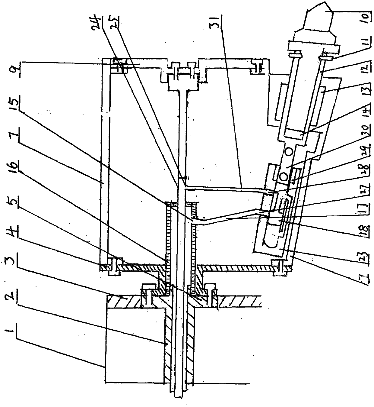
[0076] A compound rotary cutting mining machine, such as image 3 Shown, the mining machine of the compound rotary cutting of the third embodiment of the present invention, as Figure 1-2 As shown, on the basis of the first-second embodiment, the mining machine head of the composite rotary cutting of the present invention is a composite drill bit or a composite drum 7, and the inside of the mining machine main frame 1 is provided with a main shaft 2, and the power output of the main shaft 2 The shaft end 5 is fixedly connected with the connection plate 4 of the composite drill bit or the composite drum 7, and the power output shaft end 5 is arranged in cooperation with the housing 3 of the main engine 1; Inner side of spindle 2;
[0077] The high-pressure liquid pipe is connected to the drill bit or the drum at the front end of the excavation machine equipment through the mining machine main shaft 2; The connection plate 4 is fixedly connected together; the high-pressure liq...
PUM
 Abstract
Description
Claims
Application Information
 - R&D Engineer
- R&D Manager
- IP Professional
- Industry Leading Data Capabilities
- Powerful AI technology
- Patent DNA Extraction
Browse by: Latest US Patents, China's latest patents, Technical Efficacy Thesaurus, Application Domain, Technology Topic.
© 2024 PatSnap. All rights reserved.Legal|Privacy policy|Modern Slavery Act Transparency Statement|Sitemap