Condensate collecting device
A technology for collecting device and condensate, applied in lighting and heating equipment, fluid heaters, etc., can solve the problems of inability to discharge condensate, potential safety hazards, and no safety protection mechanism.
- Summary
- Abstract
- Description
- Claims
- Application Information
AI Technical Summary
Problems solved by technology
Method used
Image

Examples
Embodiment 1
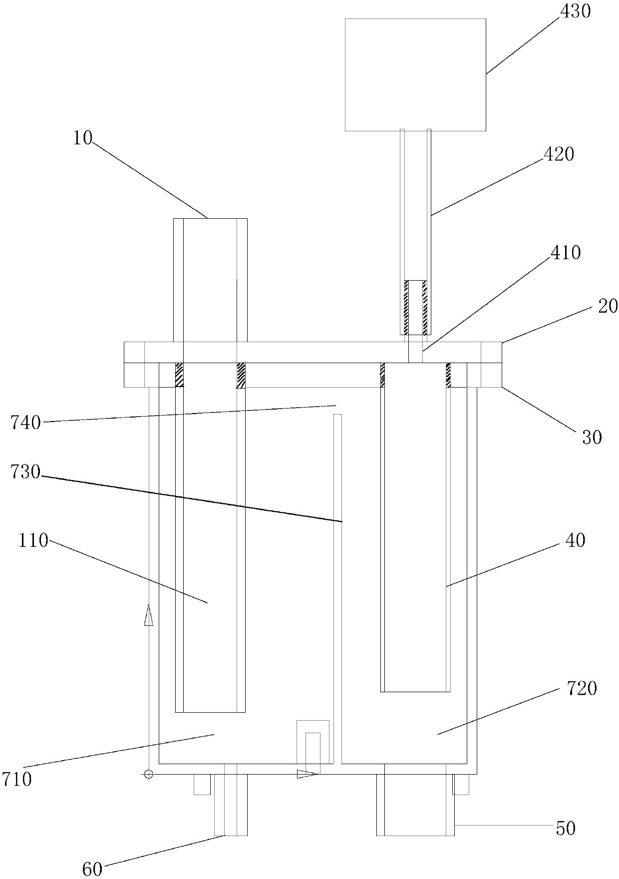
[0027] Such as figure 1 As shown, the schematic diagram of the condensate collection device described in this embodiment, the condensate collection device is provided with a water inlet 10, a condensate collection chamber for collecting and placing condensate, and an inlet connected to the water inlet 10 and extending into the condensate collection chamber. A water pipe 110 and a water outlet 50 for discharging condensate. The top of the condensate collection chamber is covered with an upper cover 20 and a lower cover 30 , the upper cover 20 and the lower cover 30 are arranged in parallel and can be connected by fasteners or the like, and there is no need for a seal between the two. Wherein the upper cover 20 and the lower cover 30 are provided with the same shape and corresponding first openings corresponding to the water inlet pipe 110, and are used to pass the water inlet pipe 110. The connections between the water inlet pipe 110 and the first opening are all sealed connect...
Embodiment 2
[0032] This embodiment is a further description of the first embodiment above, as figure 1As shown, the safety protection mechanism is an air conduction unit and a triggerable unit 430 connected to each other. The air conduction unit is a lower air chamber 40 connected from bottom to top, a connecting air pipe 410 and an upper air chamber 420. The lower air chamber 41 . The connecting air tube 410 and the upper air cavity 420 are uniform column structures, and the upper end of the upper air cavity 420 is connected with the triggerable unit 430 . The upper cover 20 and the lower cover 30 are provided with a second opening corresponding to the air conduction unit, the second opening of the upper cover 20 is used to pass through the connecting air pipe 410, the second opening of the lower cover 30 is used to pass through the lower air chamber 40, and the air conduction unit The connection mode with the second opening is a sealed connection, and a sealing ring and other mechanisms...
Embodiment 3
[0038] This embodiment is a further limitation of the second embodiment above, and the triggerable unit 430 is a water level switch or a water pressure sensor. When the drain port is blocked and cannot drain smoothly, the water level of the second chamber 720 will continue to rise, and compress the air chamber of the safety protection mechanism to realize pressure transmission, trigger the water level switch to stop safely, or trigger the water pressure sensor to alarm.
PUM
 Abstract
Description
Claims
Application Information
 - R&D
- Intellectual Property
- Life Sciences
- Materials
- Tech Scout
- Unparalleled Data Quality
- Higher Quality Content
- 60% Fewer Hallucinations
Browse by: Latest US Patents, China's latest patents, Technical Efficacy Thesaurus, Application Domain, Technology Topic, Popular Technical Reports.
© 2025 PatSnap. All rights reserved.Legal|Privacy policy|Modern Slavery Act Transparency Statement|Sitemap|About US| Contact US: help@patsnap.com