Floating location chassis riveting tool

A positioning machine and riveting technology, which is applied in the direction of electromechanical devices, manufacturing motor generators, electric components, etc., can solve the problems of non-vertical, complex mold structure, low riveting efficiency, etc., to achieve convenient and smooth removal, convenient operation, avoid The effect of positioning influence

Pending Publication Date: 2018-03-09
SUZHOU INST OF INDAL TECH
View PDF0 Cites 1 Cited by
  • Summary
  • Abstract
  • Description
  • Claims
  • Application Information

AI Technical Summary

Problems solved by technology

The traditional riveting tool needs to use the indexing structure to perform single-point riveting on the surface of the two workpieces successively. Since the two workpieces cannot be fixed well, r

Method used


Image

  • Floating location chassis riveting tool
  • Floating location chassis riveting tool
  • Floating location chassis riveting tool

Examples


Embodiment Construction

[0035] In order to make the object, technical solution and advantages of the present invention clearer, various embodiments of the present invention will be described in detail below in conjunction with the accompanying drawings.

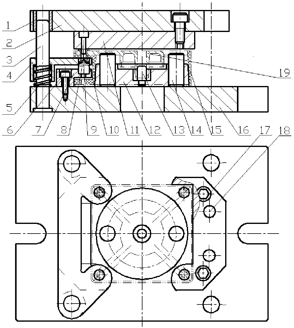
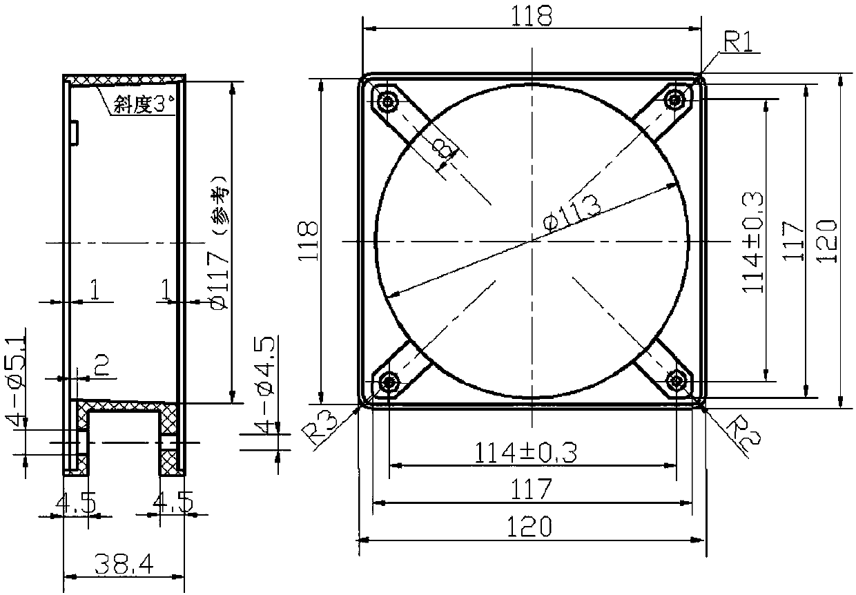
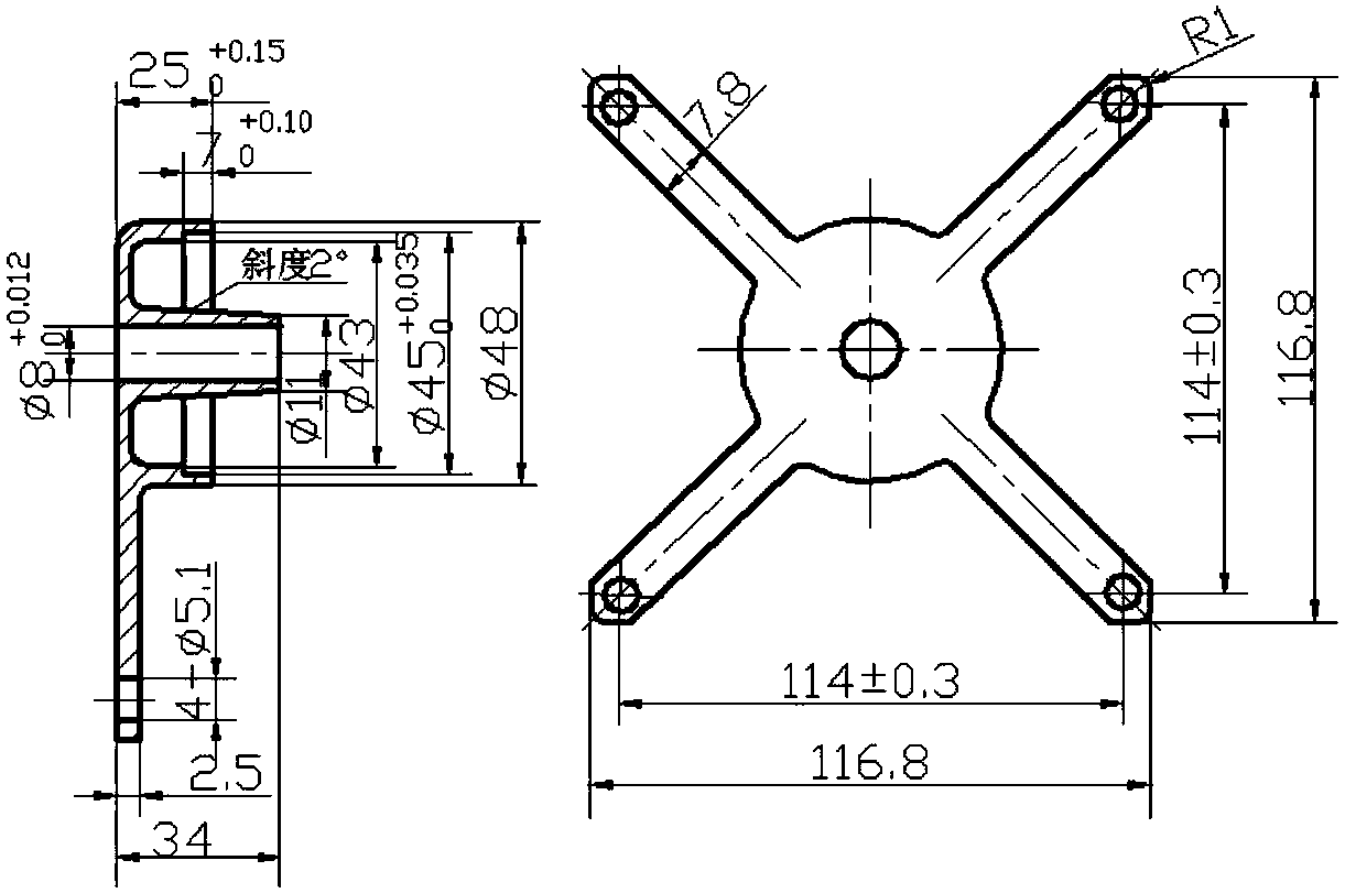
[0036] Please refer to the following Figure 1 to Figure 12 , a floating positioning casing riveting tooling (such as figure 1 Shown), used for casing 15 (such as figure 2 shown) and stator core support 19 (such as image 3 shown) through hollow rivets 10 (such as Figure 12 Shown) riveted to form a combined casing structure (such as Figure 4 shown), the riveting tooling includes an upper die set, a lower die set, a bracket hole positioning core 13, a floating positioning core 12 on the inner edge of the casing, a limit post 14 and a riveting claw 8 (such as Figure 9 As shown), place several forks of the stator core support 19 in several grooves of the casing 15, and after aligning with the corresponding mounting holes, insert the hollow rive...


PUM


Abstract

The invention discloses a floating location chassis riveting tool. The floating location chassis riveting tool is used for riveting a chassis and a stator core support by virtue of hollow rivets to form a combined chassis structure, the floating location chassis riveting tool comprises an upper mould set, a lower mould set, a support hole location core, a chassis inner edge floating location core,a limiting column and riveting claws, wherein a plurality of forks of the stator core support are arranged in a plurality of grooves of the chassis, after a plurality of corresponding mounting holesare aligned, the hollow rivets are inserted into the mounting holes respectively, then the overall structure is arranged inside the chassis inner edge floating location core in a sheathing manner, a support location core is in interference fit with the chassis inner edge floating location core, a bearing hole of the stator core support is arranged inside the support location core in a sheathing manner, the limiting column is in the interference fit with the chassis inner edge floating location core, the limiting column is used for limiting when the upper mould set is pressed downwards, the mounted assemblies and a plurality of riveting claws are arranged on the lower mould set, and a plurality of groups of riveting claws and the hollow rivets are respectively located on the same axis. Whenthe riveting tool disclosed by the invention is utilized for processing a combined type chassis structure, production efficiency is high, and chassis quality is good.

Description

technical field [0001] The invention relates to a riveting tool, in particular to a riveting tool for a floating positioning casing. Background technique [0002] In the micro motor, it is necessary to rivet the casing of the AC fan and the stator core support to form a combined casing structure. The traditional riveting tool needs to use the indexing structure to perform single-point riveting on the surface of the two workpieces successively. Since the two workpieces cannot be fixed well, repeated riveting causes the axis of the bearing chamber of the stator core bracket to be inconsistent with the end surface of the casing. Vertical, and the riveting efficiency is low, and the mold structure is complex. Contents of the invention [0003] In order to solve the above-mentioned existing technical problems, the present invention proposes a riveting tool for a floating positioning casing. [0004] The technical scheme adopted in the present invention is: [0005] A floatin...

Claims


Application Information

Patent Timeline
IPC IPC(8): H02K15/14B21J15/10B21J15/38B21J15/44
CPCH02K15/14B21J15/10B21J15/38B21J15/44Y02T10/64
Inventor 肖洪波谈正秋
Owner SUZHOU INST OF INDAL TECH
Why Eureka
Try Eureka