
Error code compensation method after forward error correction, and coding and decoding processing devices

A processing device and forward error correction technology, applied in the field of communication, can solve problems such as power budget limitation, low test efficiency, and inability to precisely adjust the power of optical modules

Inactive Publication Date: 2018-03-09
HISILICON OPTOELECTRONICS CO LIMITED
View PDF0 Cites 16 Cited by
  • Summary
  • Abstract
  • Description
  • Claims
  • Application Information

AI Technical Summary

Problems solved by technology

The long-term bit error test generally lasts for 24 hours. Once a bit error occurs, the optical module needs to be adjusted and retested. There are problems such as long test time and low test efficiency.
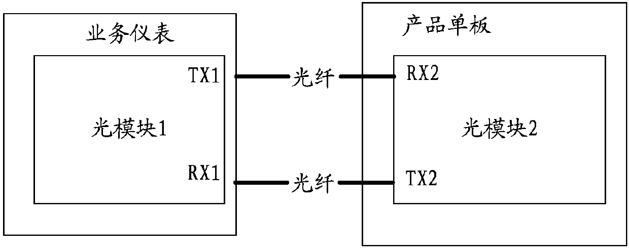
In the above test scenarios, the channel noise characteristics are estimated blindly, and the received power required by the optical module is much higher than the actual sensitivity point, so the remaining link power budget will be reduced. As the transmission port capacity increases , the power budget of the link will be further limited, which requires accurate selection of the power of the optical module, and the existing technology cannot achieve precise adjustment of the power of the optical module

Method used


Image

  • Error code compensation method after forward error correction, and coding and decoding processing devices
  • Error code compensation method after forward error correction, and coding and decoding processing devices
  • Error code compensation method after forward error correction, and coding and decoding processing devices

Examples


Embodiment Construction

[0039] Embodiments of the present invention provide a code error compensation method after forward error correction and a codec processing device, which are used to reduce code error analysis time after forward error correction and realize precise adjustment of optical module power.

[0040] In order to make the purpose, features and advantages of the present invention more obvious and understandable, the technical solutions in the embodiments of the present invention will be clearly and completely described below in conjunction with the accompanying drawings in the embodiments of the present invention. Obviously, the following The described embodiments are only some, not all, embodiments of the present invention. All other embodiments obtained by those skilled in the art based on the embodiments of the present invention belong to the protection scope of the present invention.

[0041] The terms "first", "second" and the like in the description and claims of the present invent...


PUM


Abstract

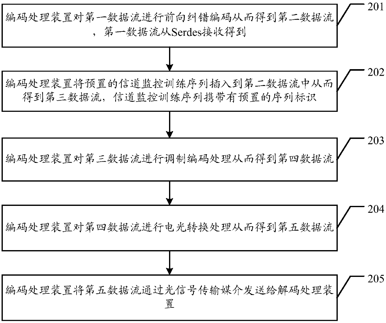
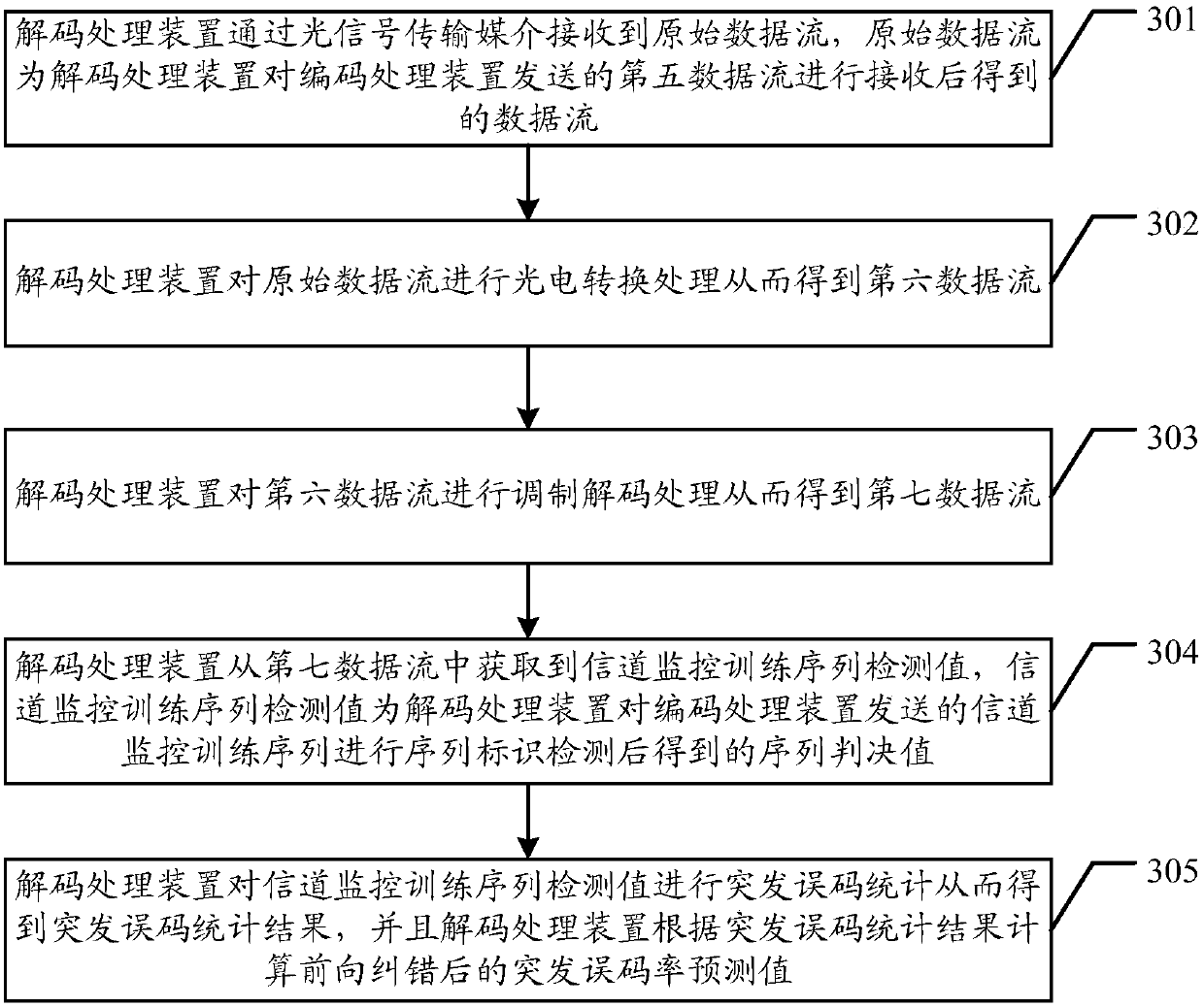
The invention discloses an error code compensation method after forward error correction, and coding and decoding processing devices, used for reducing the error code analysis time after forward errorcorrection and realizing precision adjustment on the power of an optical module at the same time, wherein the error code compensation method after forward error correction comprises the steps that: the coding processing device performs forward error correction coding on a first data flow, so that a second data flow is obtained; the first data flow is received from an Serdes; the coding processingdevice inserts a pre-set channel monitoring training sequence into the second data flow, so that a third data flow is obtained; the channel monitoring training sequence carries a pre-set sequence identifier; the coding processing device performs modulation coding on the third data flow, so that a fourth data flow is obtained; the coding processing device performs photoelectric conversion on the fourth data flow, so that a fifth data flow is obtained; and the coding processing device sends the fifth data flow to the decoding processing device through an optical signal transmission medium.

Description

technical field [0001] The present invention relates to the field of communication technology, in particular to an error code compensation method after forward error correction and a codec processing device. Background technique [0002] The rapid development of the Internet and mobile services has led to a rapid increase in the bandwidth requirements of large data centers, and the increase in the single-port rate of optical transmission modules has become an urgent need for system operators. High-order modulation schemes such as 4-order Pulse Amplitude Modulation (English full name: 4PulseAmplitude Modulation, English abbreviation: PAM4) are one of the most attractive solutions to meet the current client-side demand for large capacity and low cost. Under the condition that the single carrier bandwidth remains unchanged, the total transmission capacity of the system is doubled. Its modulation and demodulation method is also relatively simple. The sending end only needs to u...

Claims


Application Information

Patent Timeline
IPC IPC(8): H04L1/00H04L1/20H04B14/02H04B10/25
CPCH04B10/25891H04B14/023H04L1/0041H04L1/0045H04L1/203H04B10/0775H04B2210/072H04J14/0256H04L1/242H04L43/0847H04W52/20
Inventor 王传彪崔振威
Owner HISILICON OPTOELECTRONICS CO LIMITED
Learn More