Copper bar punching die

A technology of punching and mold, which is applied in the field of copper bar production, can solve the problems of slow adjustment speed of copper bar or bus bar, expensive bus bar shearing machine, low efficiency of copper bar punching, etc., and achieves production cost reduction and structure Simple, Quick Dimensional Effects

Pending Publication Date: 2018-03-13
SUZHOU TONGZHUN PRECISION PLASTIC HARDWARE CO LTD
View PDF0 Cites 1 Cited by
  • Summary
  • Abstract
  • Description
  • Claims
  • Application Information

AI Technical Summary

Problems solved by technology

[0002] In the prior art, the processing of copper bars or busbars needs to be processed by a busbar shearing machine. Because the busbar shearing machine is expensive and needs to occupy a large factory area, it makes

Method used


Image

  • Copper bar punching die
  • Copper bar punching die

Examples


Embodiment Construction

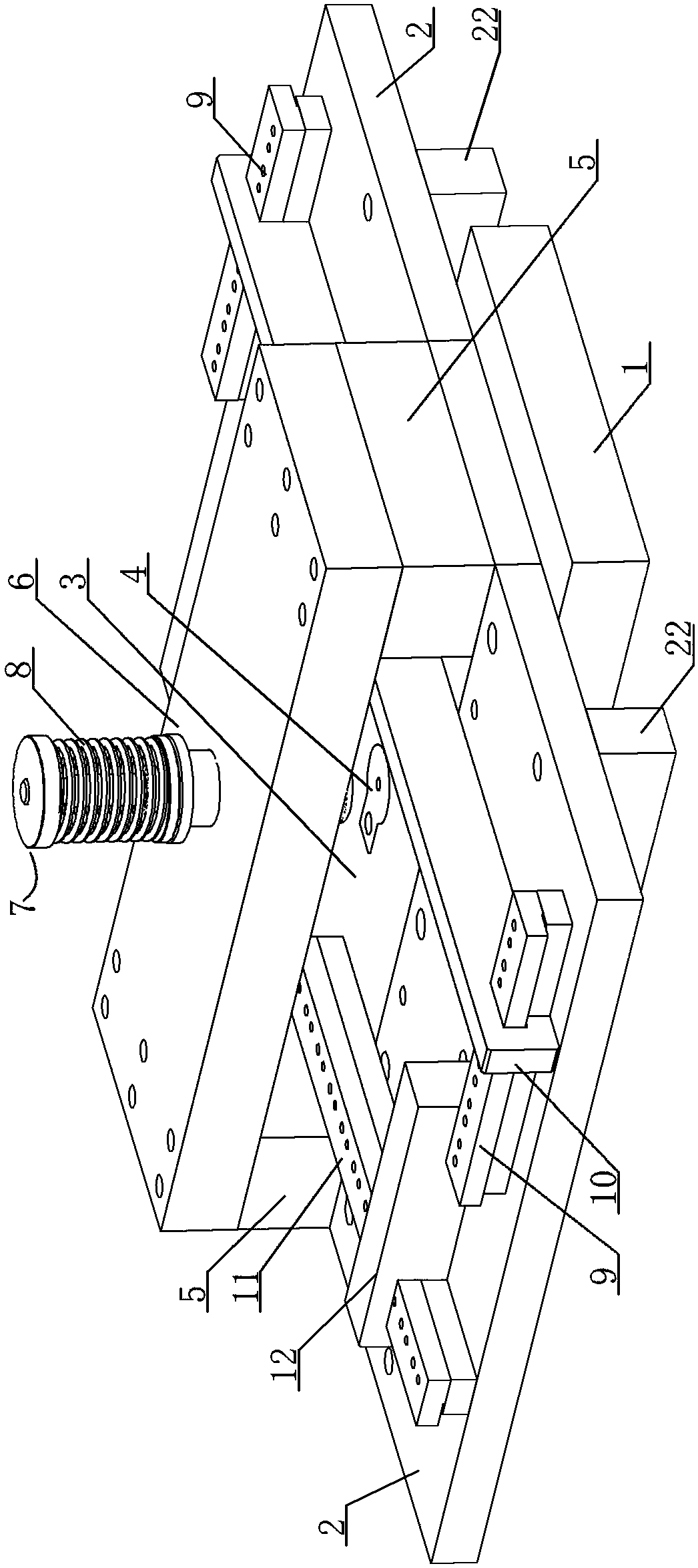
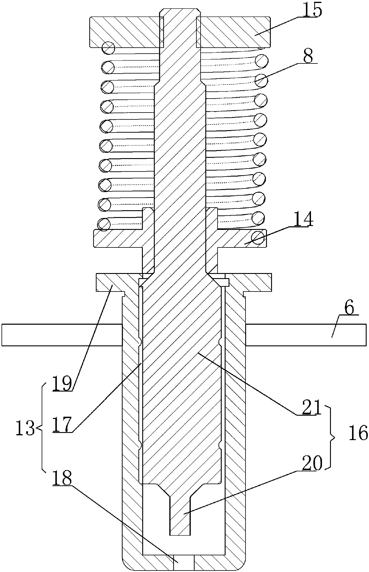
[0013] A copper bar punching die, see figure 1 , figure 2 : It includes a lower mold base 1, a lower supporting plate 2, and a lower formwork 3, the lower end surface of the lower mold base 3 is supported on the center position of the upper end surface of the lower mold base 1, and the lower supporting plate 2 is respectively arranged at both ends of the lower mold base 1 , the lower template 3 is provided with a lower mold knife edge 4, the two sides of the lower template 3 are respectively provided with vertically arranged stripper plates 5, and the two sides of the upper splint 6 are respectively supported and fastened to the stripper plates 5 on both sides The upper surface of the upper clamping plate 6 is provided with a punching tool 7, the top of the punching tool 7 is provided with a linear spring 8 to drive, the punching tool 7 protrudes from the upper clamping plate 6, and the positive part of the downward convex part of the punching tool 7 Below is the lower die e...


PUM


Abstract

The invention provides a copper bar punching die, which completes the punching of the copper bar through the mold structure, so that the structure is simple, the production cost is reduced, and the size can be quickly adjusted, so that the efficiency of the copper bar punching is high. It includes a lower mold base, a lower supporting plate, and a lower formwork, the lower end surface of the lower mold base is supported on the center position of the upper end surface of the lower mold base, and the lower supporting plates are respectively provided at both ends of the lower mold base. , the lower template is provided with a lower mold knife edge, the two sides of the lower template are respectively provided with vertically arranged stripper plates, and the two sides of the upper splint are respectively supported and fastened to the upper parts of the stripper plates on both sides. On the end face, a punching tool is arranged on the upper clamping plate, and a linear spring is arranged on the upper part of the punching tool to drive, and the lower part of the punching tool protrudes from the upper clamping plate, and the lower part of the punching tool protrudes from the upper clamping plate. Directly below is the edge of the lower die, the two lower pallets are respectively provided with first material guide strips, and the two parallel first material guide strips are provided with first stoppers.

Description

technical field [0001] The invention relates to the technical field of copper bar production, in particular to a copper bar punching die. Background technique [0002] In the prior art, the processing of copper bars or busbars needs to be processed by a busbar shearing machine. Because the busbar shearing machine is expensive and needs to occupy a large factory area, it makes the production cost high, and the existing When the busbar shearing machine is punching, the adjustment speed for copper bars or busbars of different sizes is slow, which makes the efficiency of copper bar punching low. Contents of the invention [0003] In view of the above problems, the present invention provides a copper bar punching die, which completes the punching of the copper bar through the mold structure, so that the structure is simple, the production cost is reduced, and the size can be adjusted quickly, so that the efficiency of copper bar punching is high. [0004] A copper bar punching...

Claims


Application Information

Patent Timeline
IPC IPC(8): B21D28/34
CPCB21D28/34
Inventor 陈建东
Owner SUZHOU TONGZHUN PRECISION PLASTIC HARDWARE CO LTD
Why Eureka
Try Eureka