
Integrated machine for cutting and chamfering flow collection pipe

A manifold and all-in-one machine technology, which is applied in the direction of metal processing machinery parts, other manufacturing equipment/tools, maintenance and safety accessories, etc., can solve problems such as low operation accuracy, increased handling steps, and slow operation speed, so as to increase benefits , Save labor and improve production efficiency

Pending Publication Date: 2018-03-13
SUZHOU VEDETTE IND EQUIP CO LTD
View PDF0 Cites 3 Cited by
  • Summary
  • Abstract
  • Description
  • Claims
  • Application Information

AI Technical Summary

Problems solved by technology

[0002] The header is a pipeline that collects the branch fluid to the main pipe. It is mainly used in air conditioning, fire protection and other devices. During the processing of the header, it is necessary to cut, punch, and reverse the long header. Corner operation, but at present, each station needs to be operated manually, which requires a lot of labor, and the operation speed is slow, the operation accuracy is low, and it is very inconvenient to increase the handling steps between each station

Method used


Image

  • Integrated machine for cutting and chamfering flow collection pipe
  • Integrated machine for cutting and chamfering flow collection pipe
  • Integrated machine for cutting and chamfering flow collection pipe

Examples


Embodiment Construction

[0026] The present invention will be further described below in conjunction with the accompanying drawings and specific embodiments.

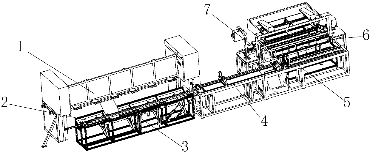
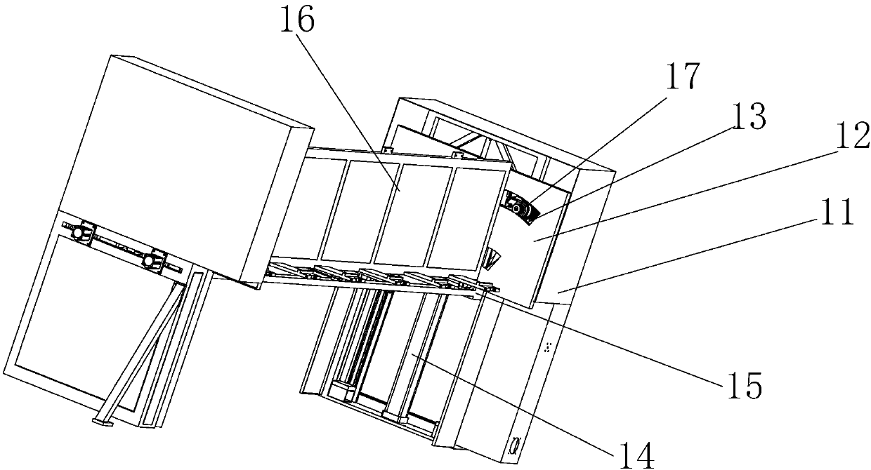
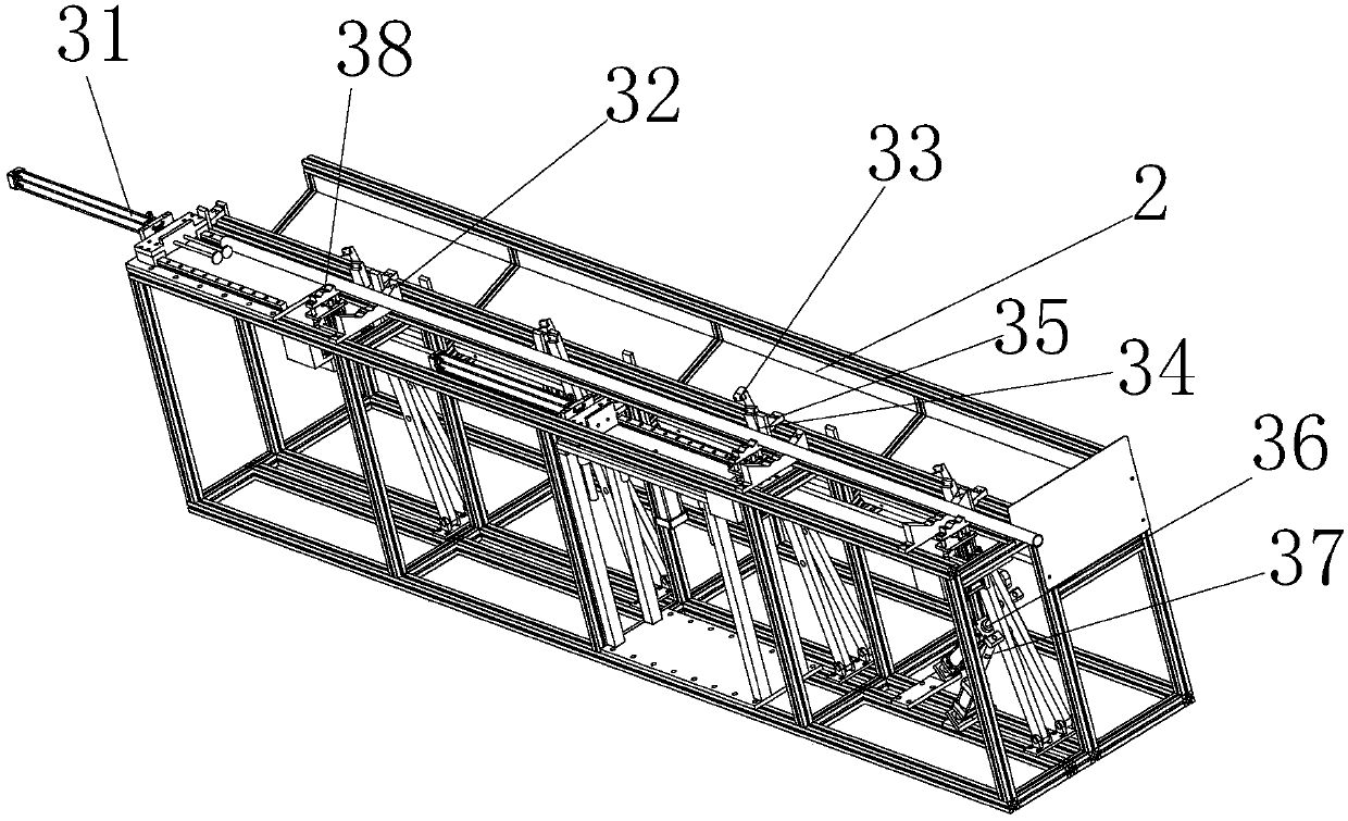
[0027] Such as figure 1 The manifold cutting and chamfering integrated machine shown includes a material rack 3 for placing the manifold, and also includes a feeding mechanism 4 and a shearing and punching mechanism 5. The material rack 3, the feeding mechanism 4 and the shearing The punching mechanism 5 is arranged in turn, and the first material pushing cylinder 31 that pushes the manifold to the feeding mechanism 4 is provided on the side of the material rack 3 away from the feeding mechanism 4, and the material frame 2 is arranged on the side of the material rack 3, The side of the material frame 2 away from the material rack 3 is provided with an auxiliary feeding mechanism 1, and the side of the shearing and punching mechanism 5 is provided with a chamfering device 7, and also includes a chamfering device arranged on the shearing and punc...


PUM


Abstract

The invention discloses an integrated machine for cutting and chamfering a flow collection pipe. The integrated machine comprises a material rack, a feeding mechanism and a cutting and punching mechanism, wherein the material rack is used for storing the flow collection pipe, and the material rack, the feeding mechanism and the cutting and punching mechanism are sequentially arranged. The side, far away from the feeding mechanism, of the material rack is provided with a first material pushing air cylinder, wherein by means of the first material pushing air cylinder, the flow collection pipe ispushed to the feeding mechanism. A material frame is further arranged at one side of the material rack. The side, far away from the material rack, of the material frame is provided with an auxiliaryfeeding mechanism. A chamfering device is arranged at one side of the cutting and punching mechanism. The integrated machine further comprises a loading mechanism, wherein the loading mechanism is arranged between the cutting and punching mechanism, and by means of the loading mechanism, the flow collection pipe is delivered into the chamfering device. By means of the cutting and chamfering integrated machine, automated production of cutting and chamfering of the flow collection pipe can be completed; production efficiency of the flow collection pipe is improved; meanwhile, manual work is saved; thus, benefits of an enterprise are increased; by means of a microscope, each welding seam can be observed through manual work conveniently; and the problem that in the punching operation process,punching is conducted on the welding seam of the flow collection pipe, so that the flow collection pipe is damaged is prevented.

Description

technical field [0001] The invention relates to the field of header processing, in particular to an integrated machine for cutting and chamfering headers. Background technique [0002] The header is a pipeline that collects the branch fluid to the main pipe. It is mainly used in air conditioning, fire protection and other devices. During the processing of the header, it is necessary to cut, punch, and reverse the long header. Corner operation, and currently in operation, each station needs to be operated manually, which requires a lot of labor, and the operation speed is slow, the operation accuracy is low, and it is very inconvenient to increase the handling steps between each station. Contents of the invention [0003] The technical problem to be solved by the invention is to provide an integrated machine for cutting and chamfering the collecting pipe which can increase the speed of cutting and chamfering the collecting pipe. [0004] The technical solution adopted by t...

Claims


Application Information

Patent Timeline
Patent Type & Authority Applications(China)
IPC IPC(8): B23P23/04B23Q11/00
CPCB23P23/04B23Q11/00
Inventor 王强魏炳峰王军
Owner SUZHOU VEDETTE IND EQUIP CO LTD
Learn More