A retractable tail brace for a flying car

A flying car and tail support technology, applied in the field of flying cars, can solve the problems of difficult take-off, increase the length of the whole vehicle, and the rear wheel is far away from the center of gravity, so as to avoid the entanglement of cable lines, reduce the vertical occupied space, and take into account the stability. Effect

Active Publication Date: 2020-06-23
BEIHANG UNIV
View PDF9 Cites 0 Cited by
  • Summary
  • Abstract
  • Description
  • Claims
  • Application Information

AI Technical Summary

Problems solved by technology

At present, there are many researches and patents on flying cars. In the design of structure and mechanism, the main focus is on the design of folding and retracting wings, which solves the problem of lateral space occupied by flying cars when driving on the ground, but ignores the The problem of its vertical footprint
[0003] Most flying cars adopt the design of the traditional aircraft tail. In order to meet the requirements of maneuverability and stability during the flight phase, the distance between the tail and the nose is relatively long, which is very redundant during the ground driving phase of the flying car and increases the weight of the whole vehicle. length, and the force arm of the negative lift of the horizontal tail on the rear wheel is long, which is not conducive to maintaining the stability of the flying car on the ground
For example, the patent with the notification number CN205202635U discloses a tail assembly for flying cars and a flying car with it. Unnecessarily increased vertical size
In addition, although the rear wheels are designed near the flat tail, which solves the stability problem of driving on the ground, the rear wheels of the flying car are far from the center of gravity, and it is difficult to lift the nose when taking off, which makes it difficult to take off.

Method used


Image

  • A retractable tail brace for a flying car
  • A retractable tail brace for a flying car
  • A retractable tail brace for a flying car

Examples


Embodiment Construction

[0022] The present invention will be described in further detail below in conjunction with the accompanying drawings.

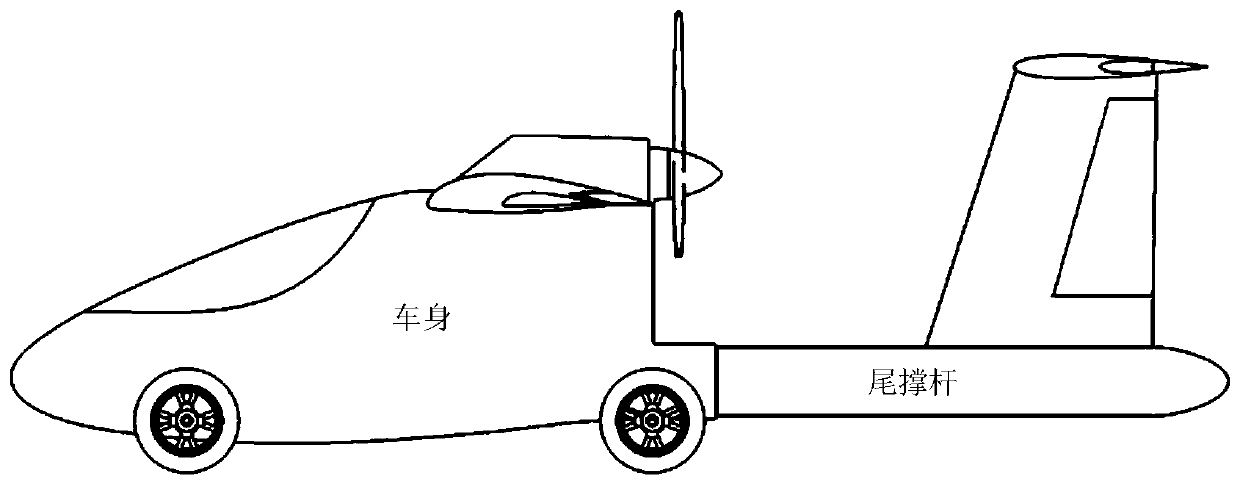
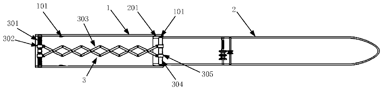
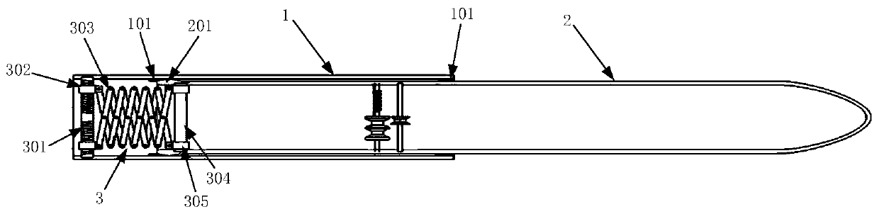
[0023] The retractable tail brace for the flying car of the present invention is installed on the rear end of the flying car body, such as figure 1 As shown, it includes front tail strut 1, rear tail strut 2 and drive system 3, such as figure 2 shown.

[0024] The rear tail strut 2 is used to install the empennage; the rear tail strut 2 is coaxially nested in the front tail strut 1 so that the rear tail strut 2 can slide axially. The outer wall of the front end of the rear tail brace 2 is designed with a boss 201 in the circumferential direction. The boss 201 is a conical boss with a front slope and a rear slope; the front inner wall of the front tail brace 1 and the rear inner wall A locking ring 101 is designed circumferentially, and the rear side of the locking ring 101 on the inner wall of the front part is an inclined plane, and the front side of the ...


PUM


Abstract

The invention discloses a retractable tail brace for a flying car, which is applied to the flying car and can effectively reduce the longitudinal space occupied by the flying car when it is running on the ground and parked. The tail stay of the present invention is divided into a front tail stay and a rear tail stay, and the expansion and contraction of the tail stay is realized by a scissors mechanism. A cable line storage device is arranged in the rear tail brace to prevent the line from being entangled. The expansion / contraction movement of the telescopic tail brace used in the flying car of the invention is stable, and the telescopic mechanism and control law are simple.

Description

technical field [0001] The invention relates to the technical field applicable to flying cars, in particular to a retractable tail brace for flying cars. Background technique [0002] A flying car is a means of transportation that combines the functions of an airplane and a car, and it needs to take into account the requirements of air flight and ground driving. At present, there are many researches and patents on flying cars. In the design of structure and mechanism, the main focus is on the design of folding and retracting wings, which solves the problem of lateral space occupied by flying cars when driving on the ground, but ignores the The problem with its vertical footprint. [0003] Most flying cars adopt the design of the traditional aircraft tail. In order to meet the requirements of maneuverability and stability during the flight phase, the distance between the tail and the nose is relatively long, which is very redundant during the ground driving phase of the flyi...

Claims


Application Information

Patent Timeline
Patent Type & Authority Patents(China)
IPC IPC(8): B60F5/02B64C5/02B64C5/06
CPCB60F5/02B64C5/02B64C5/06
Inventor 马铁林李根王养柱甘文彪张晓鸥林海英
Owner BEIHANG UNIV
Why Eureka
Try Eureka