Bottle cap tightening machine

A technology for tightening machines and bottle caps, which is applied in the direction of threaded bottle caps, bottle/container caps, sealing machines, etc. It can solve the problems of high cost, difficult maintenance, complicated lifting and rotating methods of the lifting shaft, etc., and achieves low cost and low maintenance. Easy, simple structure effect

Inactive Publication Date: 2018-03-13
乔合祥
View PDF0 Cites 10 Cited by
  • Summary
  • Abstract
  • Description
  • Claims
  • Application Information

AI Technical Summary

Problems solved by technology

[0003] Most of the existing capping machines fix a claw on the lifting shaft, and the lifting shaft drives the claw down to clamp the bottle cap, and then applies torque to the lifting shaft to drive the claw to rotate, and the claw rotates the bottle cap. ; Most of the lifting and rotating methods of the lifting shaft are very complicated, high cost, and difficult to maintain

Method used


Image

  • Bottle cap tightening machine
  • Bottle cap tightening machine
  • Bottle cap tightening machine

Examples


Embodiment Construction

[0021] The specific embodiments of the present invention will be described in further detail below in conjunction with the drawings and embodiments of the specification:

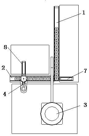
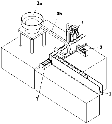
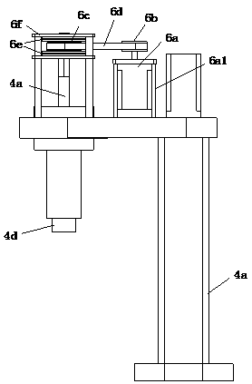
[0022] Reference Figure 1 to Figure 5 A bottle cap tightening machine shown includes a conveyor belt 1, a material rail 2, a feeding mechanism 3, and a tightening mechanism 4. The conveying direction of the conveyor belt 1 is perpendicular to the guide of the material rail 2, and the conveyor belt 1 discharges materials. The end is connected with the feeding end of the material rail 2. A pushing device matched with the material rail 2 is provided on the side of the discharge end of the conveyor belt 1. The conveyor belt 1 is used to transport the bottle body, and the bottle body is transported to the conveyor belt 1. At the end, the bottle bodies are pushed onto the material rail 2 one by one through the pushing device. The feeding mechanism 3 and the tightening mechanism 4 are distributed along the guide inte...


PUM


Abstract

The invention relates to the field of automation equipment, in particular to a bottle cap tightening machine, comprising a conveyor belt, a material rail, a feeding mechanism and a tightening mechanism, the conveying direction of the conveyor belt is perpendicular to the guide of the material rail, and the discharge end of the conveyor belt It is connected with the feeding end of the material rail, and the side of the discharge end of the conveyor belt is provided with a pushing device matched with the material rail. The feeding mechanism and the tightening mechanism are distributed along the guiding interval of the material rail. One side of the material rail A positioning device arranged opposite to the tightening mechanism is provided. The invention can realize the automatic tightening of bottle caps. The tightening mechanism adopts a rotatable rotating shaft installed inside the lifting screw rod, and a tightening head is installed at the bottom of the rotation. The lifting of the screw rod drives the rotating shaft to go up and down synchronously, and the rotation drives the tightening. The head rotates to tighten the bottle cap. The mechanism for driving the screw rod up and down and the mechanism for driving the rotating shaft are independent of each other, so that the structure is simpler, the cost is lower, and the maintenance is easier.

Description

Technical field [0001] The invention relates to the field of automation equipment, in particular to a bottle cap tightening machine. Background technique [0002] People often use a variety of bottled daily necessities in daily life, such as kitchen cleaning utensils and detergent, toilet cleaners for toilets, and shampoo bottles for shampooing. After filling, the bottle cap needs to be tightened automatically, so a capping machine or a capping machine specifically for tightening bottle caps will be involved. [0003] Most of the existing capping machines fix a claw on the lifting shaft. The lifting shaft drives the claw down to clamp the bottle cap. The lifting shaft drives the claw to rotate, and the claw rotates the bottle cap. ; Most of the lifting and rotating modes of the lifting shaft are complicated, high cost, and difficult to maintain. Summary of the invention [0004] The purpose of the present invention is to provide a bottle cap tightening machine in view of the short...

Claims


Application Information

Patent Timeline
Patent Type & Authority Applications(China)
IPC IPC(8): B67B3/20
CPCB67B3/20B67B2201/06
Inventor 乔合祥
Owner 乔合祥
Why Eureka
Try Eureka