A desktop robot automatic locking screw machine

A robot and automatic locking technology, used in metal processing equipment, metal processing, manufacturing tools, etc., can solve problems such as reducing the efficiency of screw machining, reducing the functionality and scope of application of screw machines, and inability to tighten screws. performance and scope of application, and the effect of improving practicability and use effect

Active Publication Date: 2022-04-26
星河智源(深圳)科技有限公司
View PDF5 Cites 0 Cited by
  • Summary
  • Abstract
  • Description
  • Claims
  • Application Information

AI Technical Summary

Problems solved by technology

[0003] When the current desktop robot automatic locking screw machine tightens the screw at the top of the cylindrical processed part, it cannot simultaneously tighten or unscrew the screws on different parts of the top of the processed part, which greatly reduces the practicality of the entire automatic locking screw machine. And the current automatic locking screw machine can usually only screw on the top of the cylindrical processing part, and cannot screw the periphery of the part, thus greatly reducing the functionality and scope of application of the screw machine; At the same time, the current automatic locking screw machine is to manually take out the parts and replace a new set of parts after processing a group of parts. It is impossible to place the parts on the device in advance when the automatic locking screw machine is processing the parts. Improve the processing efficiency of the whole screw machine

Method used


Image

  • A desktop robot automatic locking screw machine
  • A desktop robot automatic locking screw machine
  • A desktop robot automatic locking screw machine

Examples


Embodiment 1

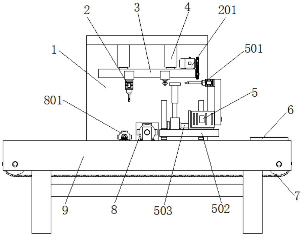
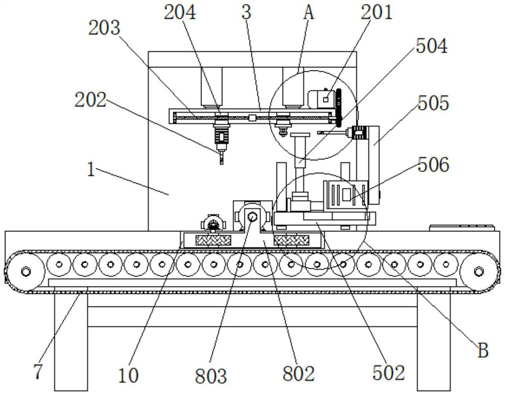
[0045] Example 1, such as figure 1 , 2 , 3, 4 and 7, when starting to tighten the screws on the top of the part, first control the first driving device 201 to drive the first threaded rod 203 to rotate, so that the two groups of sliding blocks 204 are close to or far away from each other until the infrared laser light The infrared rays emitted by 205 irradiate the screw on the top of the part, and then the second driving device 801 drives a set of scroll wheels 804 to rotate, and four sets of scroll wheels 804 are used to drive the part to rotate until the screw irradiated by the infrared laser lamp 205 turns to Directly below the first screw gun 202 , then control the extension of the first electric lifting rod 4 , and use the first screw gun 202 to tighten the screws on the parts.

Embodiment 2

[0046] Example 2, such as figure 1 , 2 , 3, 4, 5, 6 and 8, when starting to tighten the screws around the cylindrical part, control the first servo motor 506 to rotate counterclockwise 90°, so that the second screw gun 501 moves to the top of the conveyor belt device 7 At the middle position, use the clamping assembly 8 to drive the parts to rotate, so that the screws around the parts can face the second screw gun 501 one by one, and then control the electric push rod 503 to shorten, so that the second screw gun 501 can tighten the screws around the parts, And if the screws around the part are located above the outside of the part, the height of the second screw gun 501 can be controlled by shortening the second electric lifting rod 504 .

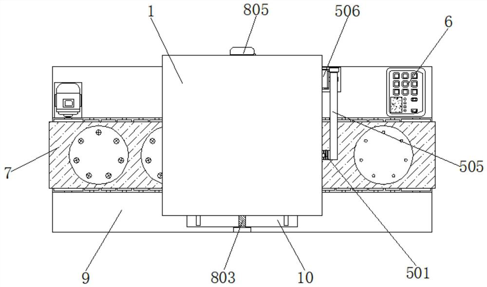
[0047] Working principle: The device is powered on before use, the operator stands at the end close to the control panel 6, and manually places the cylindrical processed parts on the top of the conveyor belt device 7, and the conveyor belt...


PUM


Abstract

The invention discloses a desktop type robot automatic locking screw machine, which comprises a mounting platform, an L-shaped main frame is installed at the middle position of one end of the mounting platform, and a second An electric lifting rod, the output ends of the two groups of the first electric lifting rods are jointly installed with a long bar, the bottom of the long bar is provided with a longitudinal processing assembly, and the middle position of the top of the installation platform is installed with a conveyor belt device . In the present invention, the L-shaped main frame, the longitudinal processing assembly, the clamping assembly, the mounting table and the mounting groove are used together. After the clamping assembly is used to drive the parts to rotate, the first screw gun can be accurately positioned on the top of the screw. Then the screw is gradually tightened on the part by the first screw gun, so as to realize the tightening of the screws at different positions on the top of the circular part, which greatly improves the practicability and use effect of the entire automatic screw locking machine.

Description

technical field [0001] The invention relates to the technical field of automatic screw locking machines, in particular to a table-top robot automatic screw locking machine. Background technique [0002] With the maturity of mechanical technology, the introduction of production lines into automated machinery has become the main trend to greatly reduce labor costs, and the introduction of automated machinery can not only reduce labor costs, but also greatly increase the overall production rate. Generally speaking, in the production of each object After completion, it is necessary to combine multiple objects to make a product. Most of the combination methods are glued or screwed. Among them, the screwed method can avoid residual glue, and it is necessary to wait for the glue to cure. It is difficult to disassemble and maintain after adhesive bonding, so screw locking is a more commonly used method for assembling objects. [0003] When the current desktop robot automatic lockin...

Claims


Application Information

Patent Timeline
Patent Type & Authority Patents(China)
IPC IPC(8): B23P19/06B23P19/00
CPCB23P19/06B23P19/00B23P19/001
Inventor 郭子丽
Owner 星河智源(深圳)科技有限公司
Why Eureka
Try Eureka