Bistable permanent magnetic three-phase breaker

A bistable and circuit breaker technology, applied in the direction of protection switch terminal/connection, protection switch operation/release mechanism, etc., can solve the problem of three-phase switch with large volume and three-phase power supply customers who have not realized cost control and poor energy saving and other problems, to achieve the effect of fast switching speed

Inactive Publication Date: 2018-03-13
STATE GRID SHANDONG ELECTRIC POWER +1
View PDF0 Cites 4 Cited by
  • Summary
  • Abstract
  • Description
  • Claims
  • Application Information

AI Technical Summary

Problems solved by technology

At present, most of the low-voltage three-phase switches (0.4kV) in the distribution network do not have the function of electric closing, and a small number of three-phase switches with electric closing function are large in size and cannot be installed in the existing electric meter box to realize cost control (prepaid electricity fee , when the electricity bill is over, the meter will control the control switch to jump open. After charging, the meter control switch will be closed. The current single-phase power supply users have realized the cost control, and the three-phase power supply customers have not realized the cost control. The main thing is stable and reliable The three-phase switch has not been developed), the price is expensive, the opening and closing of the switch requires coil energy storage, the coil will generate heat when it is energized for a long time, and the energy saving performance is not good

Method used


Image

  • Bistable permanent magnetic three-phase breaker
  • Bistable permanent magnetic three-phase breaker
  • Bistable permanent magnetic three-phase breaker

Examples


Embodiment Construction

[0018] The present invention will be further described below in conjunction with accompanying drawing:

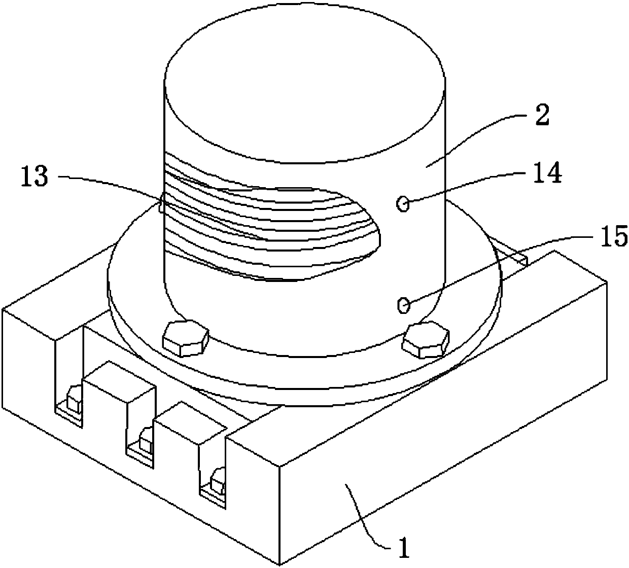
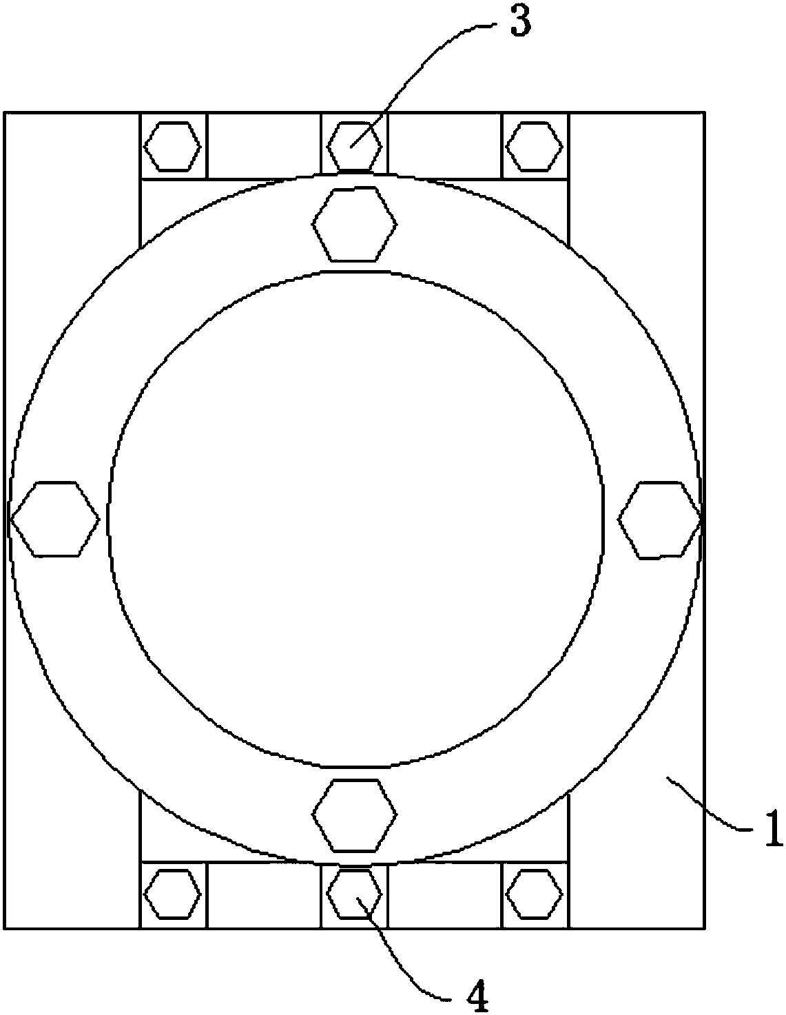
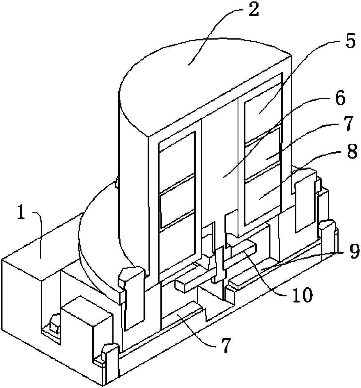
[0019] like Figure 1-Figure 4 As shown, the bistable permanent magnet three-phase circuit breaker includes a base 1, a casing 2, a three-phase wire connector 3 on the load side, and a three-phase wire connector 4 on the power supply side. The surface of the base 1 is provided with a casing 2, and the casing 2 is used to install the coil 13. A coil 13 is provided inside the casing 2, and the coil 13 is used to generate an electromagnetic field. The surface of the casing 2 is provided with an upper wiring tube 14 and a lower wiring tube 15, and the upper wiring tube 14 and the lower wiring tube 15 are used to respectively connect a DC power supply. 2 One side is provided with a load-side three-phase wire connector 3, which is used to connect the load wires, and the other side of the housing 2 is provided with a power-side three-phase wire connector 4, and the power-side thre...


PUM


Abstract

The invention discloses a bistable permanent magnet three-phase circuit breaker, which comprises a base, a casing, a load-side three-phase wire connector and a power supply-side three-phase wire connector, a casing is arranged on the surface of the base, a coil is arranged inside the casing, and a coil is arranged on the surface of the casing. For the upper wiring tube and the lower wiring tube, one side of the shell is provided with a load-side three-phase wire joint, and the other side of the shell is provided with a power-side three-phase wire joint. The upper holding permanent magnet is installed inside the shell, and a power supply is installed next to the upper holding permanent magnet. Side static contact, next to the static contact on the power supply side, there is a lower holding permanent magnet, next to the lower holding permanent magnet, a sliding iron core, under the sliding iron core, a load side moving contact, and next to the load side moving contact, a power supply side contact. The beneficial effect is that: the present invention no longer needs to maintain the electromagnets to consume energy after the state transition, and there is no noise and magnetic field effects that may be emitted when the electromagnets work continuously, and is environmentally friendly and energy-saving, and the switching speed is fast.

Description

technical field [0001] The invention relates to the field of electric power industry equipment, in particular to a bistable permanent magnet three-phase circuit breaker. Background technique [0002] A circuit breaker refers to a switching device that can close, carry and break current under normal circuit conditions and can close, carry and break current under abnormal circuit conditions within a specified time. Circuit breakers are divided into high-voltage circuit breakers and low-voltage circuit breakers according to their scope of use. The division of high and low voltage boundaries is relatively vague. Generally, those above 3,000 volts are called high-voltage electrical appliances. At present, most of the low-voltage three-phase switches (0.4kV) in the distribution network do not have the function of electric closing, and a small number of three-phase switches with electric closing function are large in size and cannot be installed in the existing electric meter box t...

Claims


Application Information

Patent Timeline
Patent Type & Authority Applications(China)
IPC IPC(8): H01H71/32H01H71/08
CPCH01H71/32H01H71/08
Inventor 冯忠奎王辉周刚李国成张晓庆冯曰敏孟庆刚张海强崔炎孟成刘新梅张瀚匀周宝凤寇承升韩永刘刚王毅许小涛徐天锡李亚洲昝浩刘广高原伊纪昌孙红艳宗飞王强燕军商同毅李想牛秋辰靳迪李雪婷孙涌
Owner STATE GRID SHANDONG ELECTRIC POWER
Why Eureka
Try Eureka