Dripping movable-joint follow-up robot arm

A technology of robot arms and joints, applied in the direction of claw arms, manipulators, manufacturing tools, etc., can solve the problems of potential safety hazards, backflow of dripping liquid, and easy safety accidents, etc., to increase the level of automation, reduce labor intensity, and avoid winding body effect

Active Publication Date: 2018-03-16
广东横琴粤澳深度合作区华发七弦琴知识产权运营服务有限公司
View PDF9 Cites 0 Cited by
  • Summary
  • Abstract
  • Description
  • Claims
  • Application Information

AI Technical Summary

Problems solved by technology

[0002] At present, the drip stand in the hospital ward is a bracket standing next to the bed. There is also a drip stand hanging on the roof of the ward. There are guide rails that can slide on the roof. The drip stand can slide in the guide rail. It is inconvenient for the patient to slide, and the drip bracket is easy to fall off, which poses a safety hazard after long-term use. The vertical bracket and the hanging bracket on the roof need to be moved by the patient to get on and off the bed, which is very inconvenient to use, and the vertical bracket prevents It is easy to fall down after being touched on the ground, breaking the medicine on the bracket, and it is easy to cause safety accidents
Existing drip brackets are all composed of a pole with hooks for hanging drip bottles, which leads to the need to turn over when the patient is sleeping, and can only be adjusted by the length of the drip delivery tube.
Because the drip delivery tube is easy to wrap around the patient's arm and body, the mild case will cause drip backflow and blood vessel blockage; the severe case may even endanger the patient's life safety
The infusion tube is easy to be entangled, causing medical accidents and endangering the life safety of the patient; and someone needs to watch the time to take care of it, which will easily lead to an increase in the workload of the medical staff and cause physical and mental fatigue

Method used


Image

  • Dripping movable-joint follow-up robot arm
  • Dripping movable-joint follow-up robot arm
  • Dripping movable-joint follow-up robot arm

Examples


Embodiment Construction

[0028] The technical solutions of the present invention will be clearly and completely described below in conjunction with the accompanying drawings. Apparently, the described embodiments are some of the embodiments of the present invention, but not all of them. Based on the embodiments of the present invention, all other embodiments obtained by persons of ordinary skill in the art without making creative efforts belong to the protection scope of the present invention.

[0029] In the description of the present invention, it should be noted that the terms "center", "upper", "lower", "left", "right", "vertical", "horizontal", "inner", "outer" etc. The indicated orientation or positional relationship is based on the orientation or positional relationship shown in the drawings, and is only for the convenience of describing the present invention and simplifying the description, rather than indicating or implying that the referred device or element must have a specific orientation, ...


PUM


Abstract

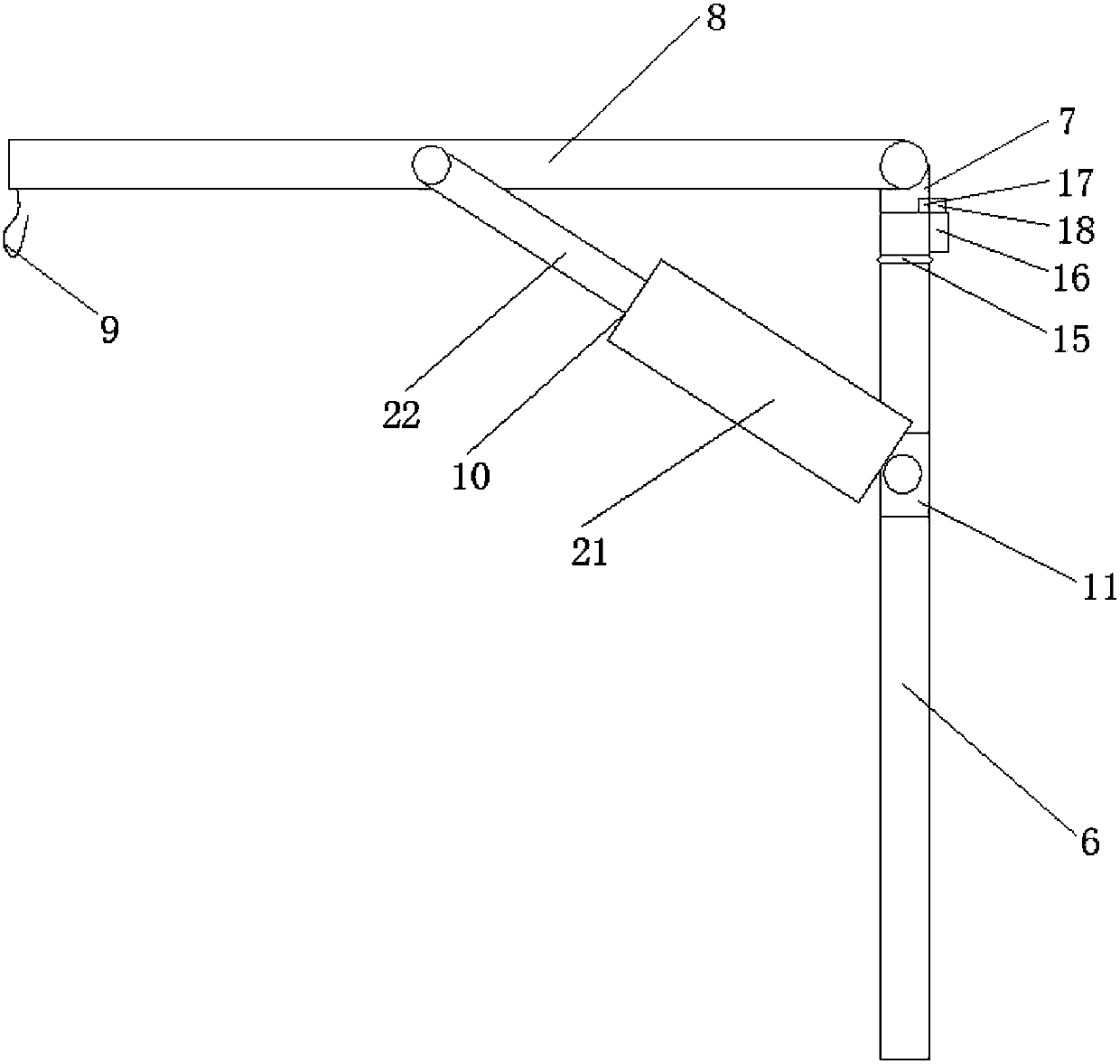
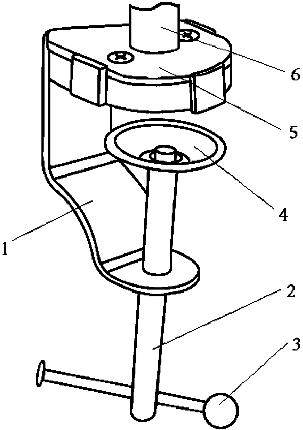
The invention relates to the technical field of dripping devices, in particular to a dripping movable-joint follow-up robot arm. The dripping movable-joint follow-up robot arm comprises a support base, a first connecting rod is arranged on the support base, one end of the first connecting rod is fixed to the support base, a rotary hinge head is arranged at the end portion of the other end of the first connecting rod and is in rotary connection with the end portion corresponding to the first connecting rod, the first connecting rod is hinged to a second connecting rod through the rotary hinge head, and an adjusting rod is arranged between the first connecting rod and the second connecting rod. Due to the fact that the dripping movable-joint follow-up robot arm is provided with the rotary hinge head and a rotary sleeve, 360-degree rotation of the dripping movable-joint follow-up robot arm can be achieved. Due to the fact that the dripping movable-joint follow-up robot arm is provided with the adjusting rod, adjustment of upper and lower angles can be achieved, and thus the length of the dripping movable-joint follow-up robot arm is adjusted. By combining the rotary hinge head, the rotary sleeve and the adjusting rod, omnibearing adjustment of the dripping movable-joint follow-up robot arm can be achieved.

Description

technical field [0001] The invention relates to the technical field of infusion equipment, in particular to an infusion joint follower robot arm. Background technique [0002] At present, the drip stand in the hospital ward is a bracket standing next to the bed. There is also a drip stand hanging on the roof of the ward. There are guide rails that can slide on the roof. The drip stand can slide in the guide rail. It is inconvenient for the patient to slide, and the drip bracket is easy to fall off, which poses a safety hazard after long-term use. The vertical bracket and the hanging bracket on the roof need to be moved by the patient to get on and off the bed, which is very inconvenient to use, and the vertical bracket prevents It is easy to fall down after being touched on the ground, break the medicine on the bracket, and easily cause safety accidents. Existing drip support all is to be made up of a pole, is provided with the hook that is used to hang drip bottle above, a...

Claims


Application Information

Patent Timeline
Patent Type & Authority Applications(China)
IPC IPC(8): B25J18/02B25J18/04B25J19/00
CPCB25J18/025B25J18/04B25J19/00
Inventor 郑焕程刘莹
Owner 广东横琴粤澳深度合作区华发七弦琴知识产权运营服务有限公司
Why Eureka
Try Eureka