Manual lifting vertical column type marking machine

A technology of lifting columns and marking machines, which is applied to typewriters, power transmission devices, printing, etc., and can solve problems such as large volume, difficult handling, and restrictions

Inactive Publication Date: 2018-03-16
张卓琳
View PDF0 Cites 0 Cited by
  • Summary
  • Abstract
  • Description
  • Claims
  • Application Information

AI Technical Summary

Problems solved by technology

[0002] There are many types of existing marking machine equipment, which are bulky and have a single appearance, making it difficult to carry
At the same time, the lifting column in the traditional marking machine is the upper end or the lower end to turn the lifting hand wheel to achieve linear motion and the volume is large, and the small equipment is limited when using the lifting column.

Method used


Image

  • Manual lifting vertical column type marking machine
  • Manual lifting vertical column type marking machine
  • Manual lifting vertical column type marking machine

Examples


Embodiment Construction

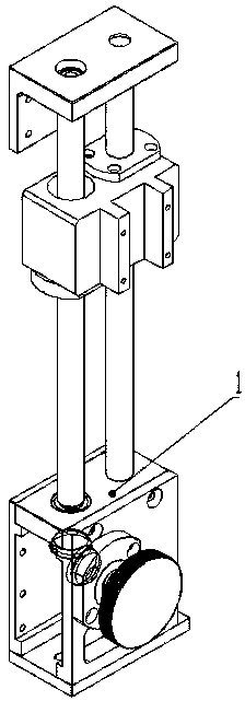
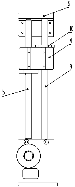
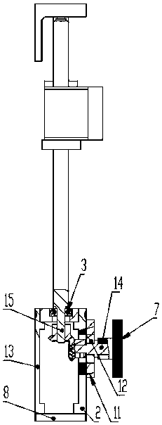
[0012] Below by non-limiting embodiment and in conjunction with accompanying drawing, invention is further described:

[0013] A manual lifting column marking machine, which includes a manual lifting column, the manual lifting column includes a lower end cover 1, a lifting block 4, a lifting screw 5, an upper end cover 6, a lifting hand wheel 7, a bottom mounting plate 8, a light Shaft 9, linear bearing 10, hand wheel seat 11, lifting bearing 14, the lifting screw 5 and the optical axis 9 are fixed side by side between the upper end cover 6 and the lower end cover 1, and the lifting block 4 is slidably arranged on the lifting screw 5 and the optical axis 9, the lower end cover 1 is surrounded by the gear box panel one 2, the gear box panel two 13, and the bottom mounting plate 8 at the bottom. The lifting handwheel 7 is fixedly installed on the lower end cover 1 through the handwheel seat 11. The lifting handwheel 7 is meshed with the lifting wheel shaft 14 and the bevel gear ...


PUM


Abstract

The invention discloses a manual lifting column marking machine, which includes a manual lifting column, and the manual lifting column includes a lower end cover, a lifting block, a lifting screw, an upper end cover, a lifting hand wheel, a bottom mounting plate, an optical axis, Linear bearings, hand wheel seats, lifting bearings, the lifting screw and the optical axis are fixed side by side between the upper end cover and the lower end cover, the lifting block is slidably arranged on the lifting screw and the optical axis, and the lower end cover is formed by the surrounding The gearbox panel and the bottom mounting plate at the bottom are enclosed. The lifting handwheel is fixedly installed on the lower end cover through the handwheel seat. The lifting handwheel is engaged with the lifting wheel shaft and the bevel gear, and the lower end of the lifting screw is meshed with the bevel gear. , the linear bearing is slidably installed on the upper end of the lifting block and meshed with the optical axis.

Description

technical field [0001] The invention relates to the field of optical fiber marking, in particular to a manual lifting column marking machine. Background technique [0002] Existing marking machines have various types of equipment, are bulky and have a single appearance, and are difficult to carry. At the same time, the lifting column in the traditional marking machine is the upper end face or the lower end face to turn the lifting handwheel to achieve linear motion and the volume is relatively large, and the use of the lifting column is limited for smaller equipment. Contents of the invention [0003] Aiming at the above defects and deficiencies in the prior art, the present invention provides a manual lifting column marking machine. [0004] The present invention is achieved through the following technical solutions: a manual lifting column marking machine, which includes a manual lifting column, and the manual lifting column includes a lower end cover, a lifting block, ...

Claims


Application Information

Patent Timeline
Patent Type & Authority Applications(China)
IPC IPC(8): B41J3/00B41J25/00
CPCB41J3/00B41J25/00
Inventor 张卓琳
Owner 张卓琳
Why Eureka
Try Eureka