Transmission system and exhaust gas turbocharger

a technology of exhaust gas and turbocharger, which is applied in the direction of machines/engines, liquid fuel engines, hoisting equipment, etc., can solve problems such as device damage, and achieve the effect of avoiding the overshooting of the permissible adjusting for

Inactive Publication Date: 2017-03-07
ROBERT BOSCH GMBH
View PDF20 Cites 0 Cited by
  • Summary
  • Abstract
  • Description
  • Claims
  • Application Information

AI Technical Summary

Benefits of technology

[0008]The transmission system exhibiting the features described herein has the advantage of avoiding the overshooting of the permissible adjusting force of the device to be adjusted.
[0010]The rolling curve radius of the driving gear and the rolling curve radius of the driven gear are matched in such a way that the driving gear and the driven gear interact in each position of the angle of rotation, in order to transfer the torque from the drive to the driver arm. If the driving gear and the driven gear are configured as gear wheels, then the rolling curve radii are to be chosen in such a way that the gear wheels engage with each other in any angle of rotation position. An appropriate choice of rolling curve radii ensures that the transmission ratio is smaller in the angle of rotation range about the extended position of the four bar coupling mechanism than outside the angle of rotation range. This achieves the objective that despite the constant torque of the drive the adjusting force acting on the coupler does not exceed the permissible adjusting force. Damage to the transmission system, the adjusting device and / or the exhaust gas turbocharger is thus avoided.
[0012]A continuous change of the transmission ratio over the angle of rotation position may be provided. This means that the first transmission ratio obtains when the driving gear is in the angle of rotation position, in which the four bar coupling mechanism is in its extended position. Starting from the first transmission ratio, the transmission ratio rises continuously so that, for example, a linear increase or an increase that follows any other rule may be provided. The above-described embodiment of the transmission system offers the advantage that the actuating time of the adjusting device may be reduced, because the average transmission ratio decreases. This means that the drive only has to perform a smaller number of revolutions, in order to achieve the same actuating effect as in the case of the adjusting devices known from the related art—that is, for example, to move the waste gate of the exhaust gas turbocharger from its open position into its closed position. Similarly the device to be adjusted is protected, as already described above, against inadmissibly high adjusting forces.
[0013]A further embodiment of the present invention provides that the driving gear and the driven gear are configured as gear wheels. This ensures a reliable transfer of the torque from the drive to the driver arm. In this case the rolling curve radii of the gear wheels have to be matched in such a way that the engagement of the gear wheels is always guaranteed. It is advantageous for the rolling curve radii to be chosen in such a way that the rate of wear of the gear wheels is as low as possible. The gear wheels exist, for example, as spur gears and may exhibit an involute tooth gearing or Wildhaber-Novikov tooth gearing.

Problems solved by technology

This may result in the device being damaged.

Method used


Image

  • Transmission system and exhaust gas turbocharger
  • Transmission system and exhaust gas turbocharger
  • Transmission system and exhaust gas turbocharger

Examples


Embodiment Construction

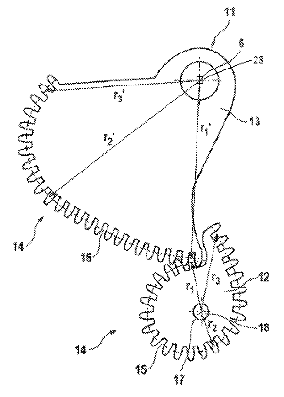
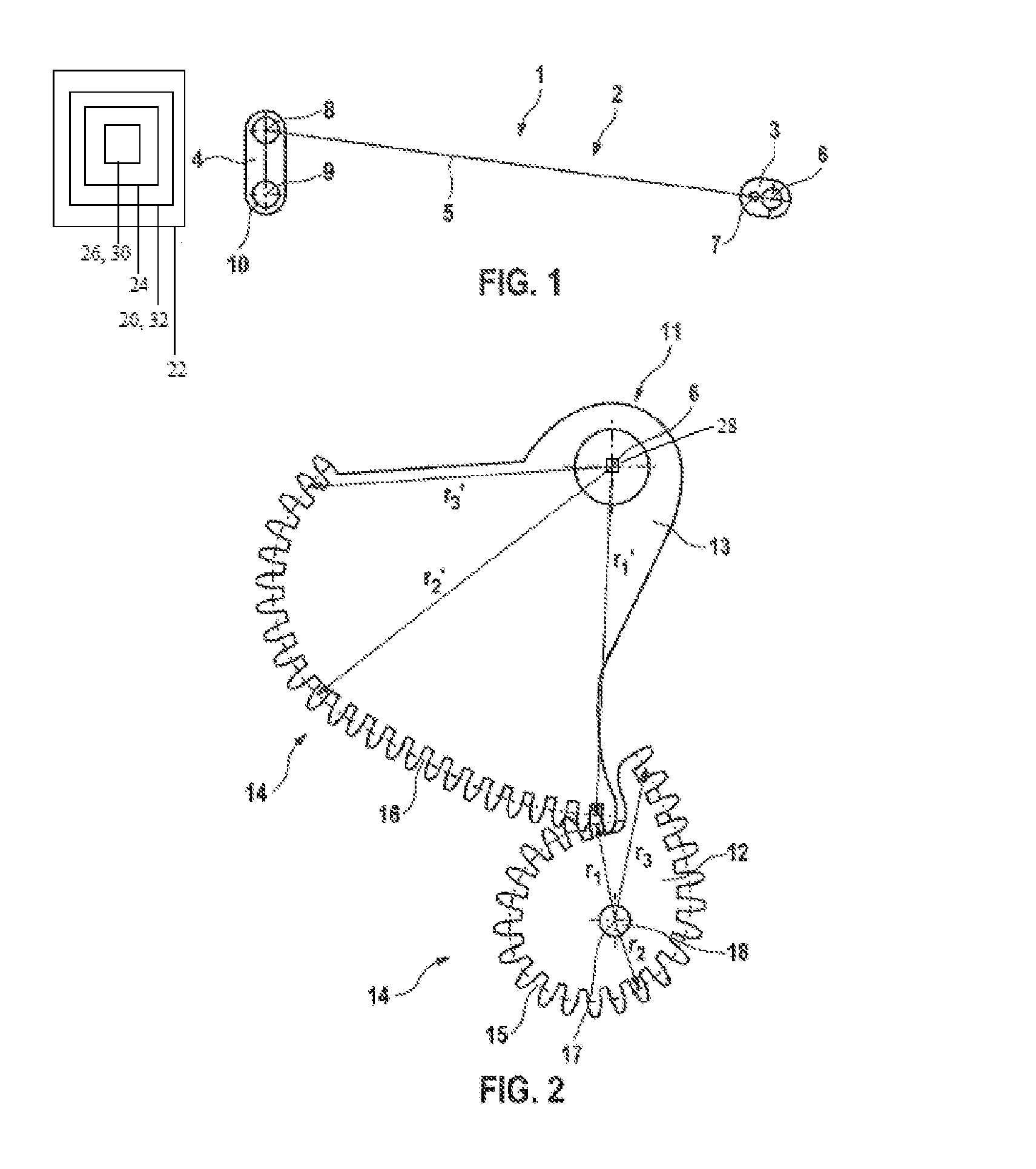
[0028]FIG. 1 is a schematic view of a transmission system 1 with a four bar coupling mechanism 2. Such a four bar coupling mechanism 2 is used, for example, for an adjusting device 24 of a waste gate 20 of an exhaust gas turbocharger 22. In this case the adjusting device 24 is an electrically operated adjusting device 24 and thus has an electric actuator or an electric drive 26. The four bar coupling mechanism 2 has a driver arm 3, an output arm 4 and a coupler 5 operatively connecting the driver arm 3 and the output arm 4. In this case the driver arm 3 is mounted so as to be rotatable about a bearing point 6. At this bearing point 6 the driver arm is operatively connected to a transmission 11 that is not shown here. Coupler 5 is mounted at a coupling bearing point 7 so as to be rotatable at the driver arm 2. The driver arm 4 has an additional coupling bearing point 8, at which the coupler 5 is mounted in a rotatable manner on the output arm 4. The output arm 4 is mounted in a rotat...


PUM


Abstract

A transmission system for an adjusting device, of a waste gate of an exhaust gas turbocharger, including a four bar coupling mechanism, a driver arm operatively connected to a drive via a transmission, an output arm and a coupler, operatively connecting the driver and output arms, the transmission having a driving gear, assigned to the drive, and a driven gear, assigned to the driver arm and interacting with the driving gear having a rolling curve radius, which changes over the circumference, the driven gear having a rolling curve radius running complementary to the former. The rolling curve radii is selected in an angle of rotation range about the extended position of the coupling to form at least in regions a first transmission ratio and outside the angle of rotation range to form at least a second transmission ratio larger than the first ratio. Also described is an exhaust gas turbocharger.

Description

FIELD OF THE INVENTION[0001]The present invention relates to a transmission system for an adjusting device, in particular, of a waste gate of an exhaust gas turbocharger, including a four bar coupling mechanism, which has a driver arm that is operatively connected to a drive via a transmission, an output arm and a coupler, which operatively connects the driver arm and the output arm; the transmission having a driving gear, assigned to the drive, and a driven gear, which is assigned to the driver arm and interacts with the driving gear. Furthermore, the present invention relates to an exhaust gas turbocharger.BACKGROUND INFORMATION[0002]Exhaust gas turbochargers equipped with a waste gate, which are adjustable by an adjusting device or an actuating drive, are known from the related art. The actuating drive can be configured, for example, as a pneumatic actuating drive. However, as an alternative, the actuation or adjustment of the waste gate can also be achieved by an electric actuat...

Claims


Application Information

Patent Timeline
Patent Type & Authority Patents(United States)
IPC IPC(8): F02D23/00F02B37/18
CPCF02B37/186Y02T10/144Y10T74/19884Y02T10/12F02B37/12F02B39/04
Inventor BAEUERLE, MICHAELNAU, MICHAEL
Owner ROBERT BOSCH GMBH
Why Eureka
Try Eureka