A cable cutting device

A cutting device and cable technology, which is applied in the field of electric auxiliary equipment, can solve problems such as discharge at the tip of the cable cut, difficulty in controlling the depth and stability of the cut, and insufficient tightness of the cable connection.

Active Publication Date: 2021-09-14
RES INST OF ECONOMICS & TECH STATE GRID SHANDONG ELECTRIC POWER +3
View PDF9 Cites 0 Cited by
  • Summary
  • Abstract
  • Description
  • Claims
  • Application Information

AI Technical Summary

Problems solved by technology

[0002] Cable is an essential part of the operation of the power system. The production and installation of cable lines is closely related to the safe operation of the power system. During the process of making and installing cable lines, it is necessary to cut the cables. However, operators generally rely on their senses and experience. After the cable is cut, it is difficult to control the depth and smoothness of the cut during operation, and it is impossible to ensure that the fracture and chamfer of the cable are smooth and smooth, so it is easy to cause the cable and the cable accessories to not be tightly overlapped, and it is easy to cause a tip discharge at the cable cut, resulting in The two sections of cables cannot be connected tightly, leaving potential safety hazards;
[0003] There are many devices for cutting cables in the prior art, but the copper wire at the incision of the cut cable will produce many burrs, resulting in insufficient tight connection of the cables on both sides, and manual grinding of the cable ends is often required to remove the ends. Burrs to quickly meet production requirements for safety cable routes

Method used


Image

  • A cable cutting device
  • A cable cutting device
  • A cable cutting device

Examples


Embodiment 1

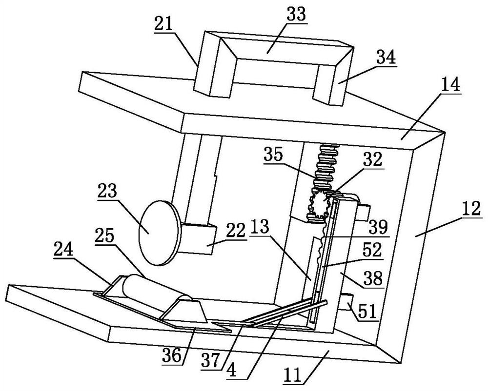
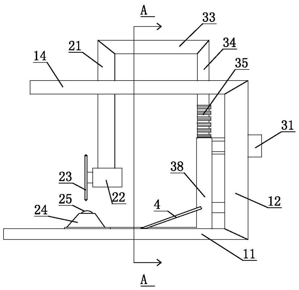
[0029] The present invention is a cable cutting device, comprising a base 11, a support 12 is provided on the upper part of the base 11, an outlet 13 is provided at the bottom of the support 12, a side support plate 14 is provided on the support 12, the Side support plate 14 is provided with elevating rod 21, and described elevating rod 21 is slidably connected with side support plate 14, and the end portion of described elevating rod 21 is fixedly connected with first motor 22, and the output end of described first motor 22 is provided with There is a cutter 23, the base 11 is provided with a support frame 24, and the support frame 24 is rotatably connected with a roller 25. When cutting the cable, the cable is placed on the roller 25, and the place to be cut on the cable is Mark and align the mark with the cutter 23. At this time, the roller 25 pushes the cable to be cut to the highest point, and the cutter 23 runs downward. The cutter 23 will cut the protruding part of the c...

Embodiment 2

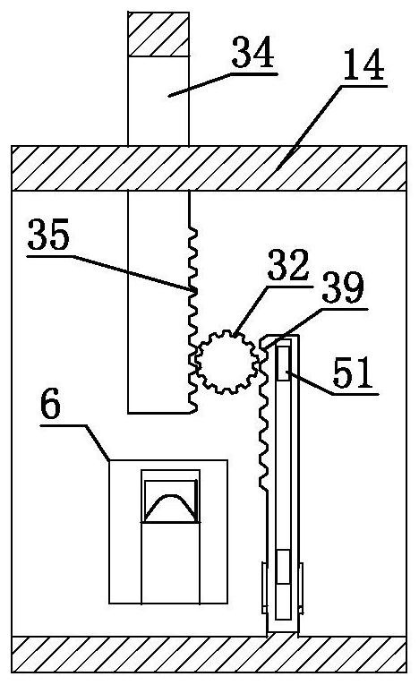
[0034] The present invention is a cable cutting device. On the basis of Embodiment 1, in order to ensure the stability in the cutting process, a cable fixing mechanism 6 is provided on the base 11 and in the outlet 13, and the cable fixing Mechanism 6 comprises fixed frame 61, and described fixed frame 61 interior is provided with chute 62 and moving block 63, and described moving block 63 is provided with cable fixing opening 64, and described moving block 63 bottom is provided with spring 65, and described spring 65 is fixedly connected with the base 11, and the cable fixing mechanism 6 can fix the state of the two ends of the cable to prevent the cable from slipping during the cutting process and ensure the stability during the cutting process.

[0035] In order to further ensure the stability of the operation of the whole device, the roller 25 is provided with a plurality of transverse grooves 66, and the transverse grooves 66 cooperate with the cutter 23 to prevent the cut...


PUM


Abstract

The invention discloses a cable cutting device and relates to the technical field of electric power auxiliary equipment. Including the base, the upper part of the base is provided with a support, the bottom of the support is provided with an outlet, the support is provided with a side support plate, the side support plate is provided with a lifting rod, and the end of the lifting rod is provided with A first motor, a cutter is provided at the output end of the first motor, a support frame is provided on the base, and rollers are rotatably connected to the support frame. The beneficial effect of the present invention is that it can ensure that a large number of burrs will not appear at the cut of the cable when the cable is cut.

Description

technical field [0001] The invention relates to the technical field of electric power auxiliary equipment, in particular to a cable cutting device. Background technique [0002] Cable is an essential part of the operation of the power system. The production and installation of cable lines is closely related to the safe operation of the power system. During the process of making and installing cable lines, it is necessary to cut the cables. However, operators generally rely on their senses and experience. After the cable is cut, it is difficult to control the depth and smoothness of the cut during operation, and it is impossible to ensure that the fracture and chamfer of the cable are smooth and smooth, so it is easy to cause the cable and the cable accessories to not be tightly overlapped, and it is easy to cause a tip discharge at the cable cut, resulting in The two sections of cables cannot be connected tightly, leaving potential safety hazards; [0003] There are many de...

Claims


Application Information

Patent Timeline
Patent Type & Authority Patents(China)
IPC IPC(8): B21F11/00
CPCB21F11/00
Inventor 韩义成姜兆庆薛炳磊宋来森亓超程剑
Owner RES INST OF ECONOMICS & TECH STATE GRID SHANDONG ELECTRIC POWER
Why Eureka
Try Eureka