Valve rod sealing structure and valve

A technology of sealing structure and valve stem, which is applied to shaft seals, valve details, valve devices, etc., can solve the problems of easy failure and leakage of the valve stem sealing structure, large power consumption required for valve action, etc., and achieves simple structure and compact valve structure. , The effect of valve sealing performance is good

Pending Publication Date: 2020-06-09
NEWAY VALVE SUZHOU
View PDF0 Cites 3 Cited by
  • Summary
  • Abstract
  • Description
  • Claims
  • Application Information

AI Technical Summary

Problems solved by technology

[0004] Therefore, the technical problem to be solved by the present invention is to overcome the defects in the prior art that the valve stem sealing structure is prone to failure and leakage, and the power consumption required for valve action is relatively large.

Method used


Image

  • Valve rod sealing structure and valve
  • Valve rod sealing structure and valve
  • Valve rod sealing structure and valve

Examples


Embodiment 1

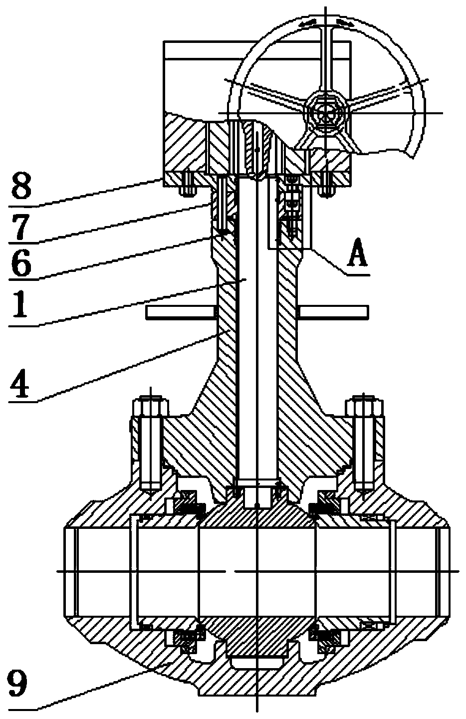
[0033] This embodiment provides a valve stem sealing structure, such as figure 2 As shown, it includes a valve stem 1 , a valve cover 4 and a pan-seal ring 61 .

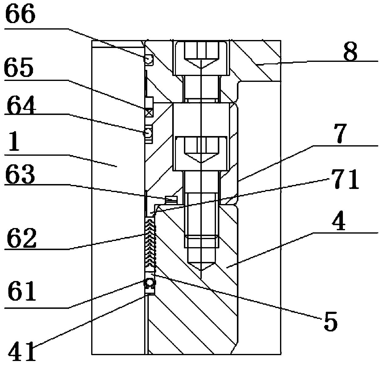
[0034] Among them, the valve cover 4 is set outside the valve stem 1; the inner wall of the valve cover 4 has a first annular groove 41, and a packing groove 5 is provided between the outer wall of the valve stem 1 and the inner wall of the valve cover 4; the first annular groove 41 It is surrounded with the valve stem 1 to form a stuffing groove 5;

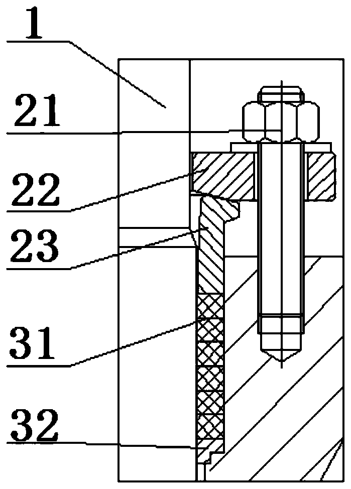
[0035] The valve stem sealing structure of this structure is applied to the valve without setting the pressure plate 22 and the pressure sleeve 23. The structure is simple and saves space, making the valve structure compact; the medium circulating in the valve body generates a medium force, and the medium force acts from bottom to top For the Variseal ring 61, the Varioseal ring 61 is deformed by force, and its inner and outer sides are respectively attached to the va...

Embodiment 2

[0054] This embodiment provides a ball valve, such as figure 2 As shown, it includes the valve body 9 and the valve stem sealing structure in Embodiment 1.

[0055] There is no need to set the pressure plate 22 and the pressure sleeve 23 in the ball valve, the structure is simple, the space is saved, and the valve structure is compact; when the valve is installed, there is no need to apply pretightening force to the packing first, and the friction torque of the valve stem 1 is small when the valve is opened and closed, and the power consumption is small; The greater the medium pressure, the better the valve sealing performance.

[0056] As a modification, the valve stem sealing structure in Embodiment 1 can also be applied to other sealing structures, such as gate valves or butterfly valves.


PUM


Abstract

The invention provides a valve rod sealing structure and a valve. The valve rod sealing structure comprises a valve rod, a valve cover and a spring ring, wherein the valve comprises the valve rod sealing structure; the valve cover sleeves the valve rod; a first annular groove is formed in the inner wall surface of the valve cover; a filler groove is formed between the outer wall of the valve rod and the inner wall of the valve cover; and the spring ring sleeves the valve rod, and is positioned in the filler groove. The valve rod sealing structure with the structure is applied to the valve without needing to arrange a pressing plate and a pressing sleeve, is simple in structure, saves the space, and is compact in structure; the spring ring is deformed by medium force, and the inner side andthe outer side are correspondingly bonded on the valve rod and the valve cover to realize sealing between the valve rod and the valve cover; when the valve rod sealing structure is mounted, pretightening force is not needed to be applied to fillers; when the valve rod performs a rotating motion or a linear motion, the friction torque of the valve rod is low, so that the torque of the valve duringopening and closing is reduced, and the opening and closing power consumption of the valve is reduced; the medium force is high, so that the spring ring is high in stress deformation, and the sealingof the spring ring is more reliable; and the valve rod sealing structure can be used on various valves.

Description

technical field [0001] The invention relates to the technical field of valve equipment, in particular to a valve stem sealing structure and a valve. Background technique [0002] Nowadays, the society pays more and more attention to environmental protection. Many valves are required to meet the low leakage requirements, and the packing of the valve stem can easily cause damage to the packing due to the opening and closing of the valve stem, resulting in leakage, which is harmful to the environment, equipment and even life. Such as figure 1 As shown, the valve stem seal structure in the prior art includes packing 31, packing pad 32, pressure plate 22, pressure sleeve 23, studs and nuts 21, etc., the studs are passed through the pressure plate 22, and the nut 21 is located above the pressure plate 22, The packing 31 and the packing pad 32 are sleeved on the valve stem 1 and located on the lower side of the pressure sleeve 23 . [0003] When the valve is installed, the nut 21...

Claims


Application Information

Patent Timeline
Patent Type & Authority Applications(China)
IPC IPC(8): F16K41/02F16K41/04
CPCF16K5/0694F16K41/02F16K41/04
Inventor 涂楠高仁杰
Owner NEWAY VALVE SUZHOU
Why Eureka
Try Eureka