superstructure

A vehicle body and bending technology, which is applied to the superstructure, superstructure sub-assemblies, vehicle components, etc., can solve problems such as rising costs, reduce the weight of the vehicle body, and improve the torsional rigidity and side impact performance.

Active Publication Date: 2020-09-04
SUZUKI MOTOR CORP
View PDF9 Cites 0 Cited by
  • Summary
  • Abstract
  • Description
  • Claims
  • Application Information

AI Technical Summary

Problems solved by technology

[0009] In addition, when high-tensile steel is used for the vehicle body in order to improve the side impact performance of the vehicle body, there is a problem of cost increase

Method used


Image

  • superstructure
  • superstructure
  • superstructure

Examples


no. 1 approach

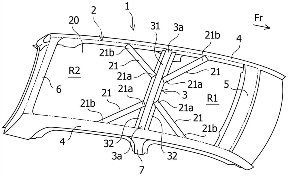
[0022] figure 1 and figure 2 Both show the vehicle body superstructure according to the first embodiment of the present invention.

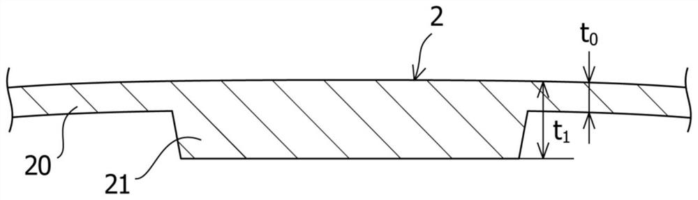
[0023] Such as figure 1 and figure 2 As shown, the upper vehicle body 1 of the vehicle to which the structure according to the first embodiment of the present invention is applied mainly includes a resin roof 2, a roof cross member 3 extending in the vehicle width direction, Extended roof rails 4 located on the left and right sides, and roof front rails 5 and roof rear rails 6 extending in the vehicle width direction at the front and rear ends of the vehicle body, respectively. The resin roof 2 is a resin plate or the like for reducing the weight of the vehicle body. The resin roof 2 is the peripheral parts of the roof rails 4 located on the left and right sides of the vehicle body upper part 1 and the roof front beam 5 and the roof rear beam 6 respectively located at the front and rear ends of the vehicle body upper part 1, and is arrang...

no. 2 approach

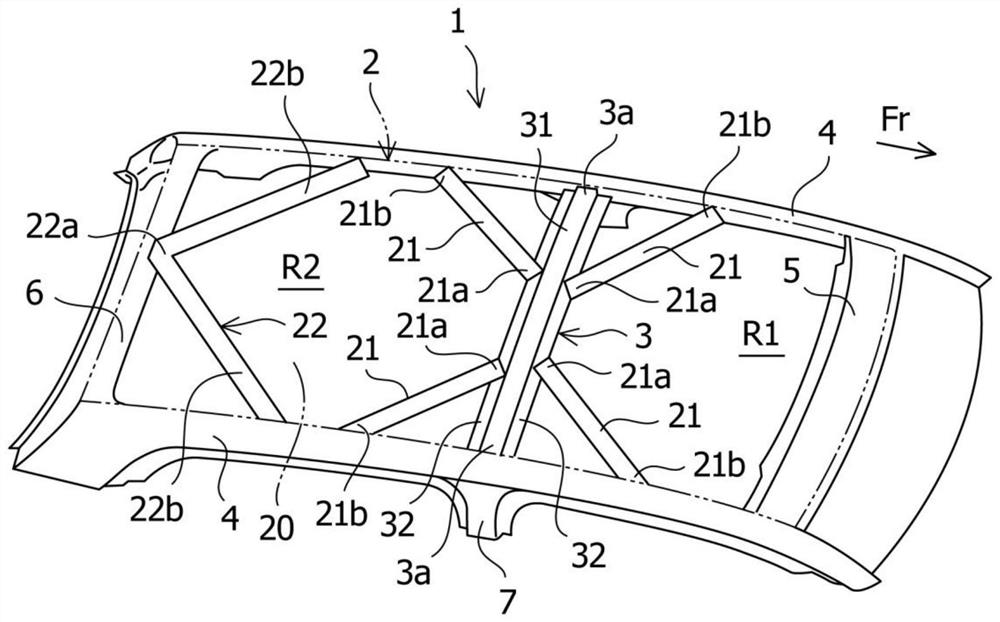
[0039] image 3 A vehicle body superstructure according to a second embodiment of the present invention is shown. The same parts as those described in the above-mentioned first embodiment are denoted by the same reference numerals, and description thereof will not be repeated.

[0040] In the vehicle body upper part 1 according to the second embodiment, in addition to the structure according to the first embodiment, as image 3 As shown, a highly rigid portion 22 that joins the roof rear rail 6 with the respective roof rails 4 on the left and right sides is also disposed on the rear end side in the vehicle rear region R2. The high-rigidity portion 22 on the rear end side includes a beam engaging portion 22a at which the roof rear rail 6 is engaged and a side beam engaging portion 22b extending in an oblique direction toward the vehicle front and at the beam engaging portion 22b. The junction part 22a is branched into a corresponding one of the roof rails 4 extending to the l...


PUM


Abstract

The invention provides an upper structure of a vehicle bodywork. Torsional rigidity and side face collision performance of a vehicle bodywork can be improved and weight reduction of the vehicle bodywork is achieved in case that enhancement components are not increased. The upper structure includes a resin roof (2), a roof beam (3) in a vehicle width direction, and roof rails (4) on the right and left sides in a longitudinal direction of vehicle on the right and left sides of a vehicle body, the roof (2) having portions of high rigidity (21) each having greater rigidity than other normal portions (20) of the roof (2), each high stiffness portion (21) being at an angle of an intermediate portion of the roof beam (3) in the vehicle width direction to one of the corresponding roof rails (4) onthe right and left sides and each high rigidity portion (21) being in a vehicle front side region (R1) or a vehicle rear side region (R2) on each side of the roof beam (3).

Description

technical field [0001] The invention relates to the superstructure of a vehicle body. Background technique [0002] Conventionally, there is known a technique of molding a roof in an upper portion of a vehicle body using a resin material in order to reduce the weight of the vehicle body. Also, when a resin roof is used instead of a steel roof, the torsional rigidity of the vehicle body and the performance of the vehicle body in a side impact generally deteriorate. [0003] Therefore, in the conventional vehicle body upper structure, there is a technique for providing ribs at each of the four corners of the resin roof panel to improve the rigidity of the vehicle body (for example, refer to Patent Document 1). [0004] prior art literature [0005] patent documents [0006] Patent Document 1: Japanese Patent No. 5494835 Contents of the invention [0007] The problem to be solved by the invention [0008] Unfortunately, the structure provided with ribs at the corners of...

Claims


Application Information

Patent Timeline
Patent Type & Authority Patents(China)
IPC IPC(8): B62D25/06B62D29/04
CPCB62D25/06B62D29/043
Inventor 村瀬祐大长岛洋明
Owner SUZUKI MOTOR CORP
Why Eureka
Try Eureka