Supercharge Your Innovation With Domain-Expert AI Agents!

Cable erecting device

A cable and accommodating slot technology is applied in the field of cable erection devices, which can solve the problems of easy tilting of electric poles and poor fixing effect, and achieve the effects of improving work efficiency, simple structure and improving stability.

Active Publication Date: 2018-03-16
江苏源清环保科技有限公司
View PDF7 Cites 0 Cited by
  • Summary
  • Abstract
  • Description
  • Claims
  • Application Information

AI Technical Summary

Problems solved by technology

[0002] The power cable is an important carrier of the communication network, and the erection of the power cable needs the support of the electric pole. After the electric pole is placed in the pit dug on the surface, the soil needs to be covered and compacted to increase the stability of the electric pole. The traditional The method is to be solidified by electric power workers with tools such as shovels. However, in order to strengthen the fixing effect, the surface soil layer needs to be piled up into a slope shape, and it is difficult to make the soil layer uniform in density by manual compaction, which makes the pole easy to tilt and the fixing effect is poor.

Method used


Image

  • Cable erecting device
  • Cable erecting device
  • Cable erecting device

Examples


Embodiment Construction

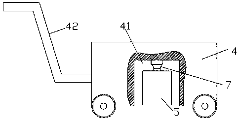
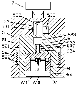
[0018] Such as figure 1 , figure 2 and image 3 As shown, a cable erection device of the present invention includes a push car body 4, a push handrail 42 is fixedly arranged on the left side of the push car body 4, a hollow cavity 41 is arranged in the push car body 4, and the The hollow cavity 41 is fixedly provided with a corner hanger device 7 and a knocker 5 installed at the bottom of the corner hanger device 7, the bottom surface of the knocker 5 is provided with a first container 51, and the first container Sliding and knocking blocks 6 are connected in sliding fit in 51, and the inner walls on the left and right sides of the first container 51 are oppositely provided with guide devices respectively cooperating with the outer walls on the left and right sides of the sliding knocking blocks 6, so The top wall of the first container 51 is provided with a knocking and driving device, and the bottom surface of the sliding knocking block 6 is provided with a sinking groove...


PUM


Abstract

The invention discloses a cable erecting device comprising a push-moving vehicle body. A push-moving handrail is fixedly arranged on the left side face of the push-moving vehicle body, a hollow cavityis formed in the push-moving vehicle body, the hollow cavity is internally and fixedly provided with a corner hanging piece device and a knock-compacting machine mounted at the bottom of the corner hanging piece device, and a first containing groove is formed in the bottom face of the knock-compacting machine. A sliding knock-compacting block is connected into the first containing groove in a sliding fit mode, moving guiding devices connected with the outer walls of the left side and the right side of the sliding knock-compacting block in a matched mode correspondingly are oppositely arrangedon the inner walls of the left side and the right side of the first containing groove, and a knock-compacting drive-moving device is arranged in the inner top wall of the first containing groove. A sinking groove is formed in the bottom face of the sliding knock-compacting block, a sliding groove is formed in the position, on the upper side of the sinking groove, of the sliding knock-compacting block, and a channel groove is formed in the position, between the bottom of the sliding groove and the bottom wall of the sinking groove, of the sliding knock-compacting block in a through mode. According to the cable erecting device, the structure is simple, operating is convenient, the drive-moving work of knock-compacting operation can be automatically controlled, the labor amount of workers isdecreased, and the work efficiency and quality are improved.

Description

technical field [0001] The invention relates to the field of electric power technology, in particular to a cable erecting device. Background technique [0002] The power cable is an important carrier of the communication network, and the erection of the power cable needs the support of the electric pole. After the electric pole is placed in the pit dug on the surface, the soil needs to be covered and compacted to increase the stability of the electric pole. The traditional The method is to be solidified by electric power workers with tools such as shovels. However, in order to strengthen the fixing effect, the surface soil layer needs to be piled up into a slope shape, and it is difficult to make the soil layer uniform in density by manual compaction, which makes the pole easy to tilt and the fixing effect is poor. . Contents of the invention [0003] The technical problem to be solved by the present invention is to provide a cable erection device, which can solve the abo...

Claims


Application Information

Patent Timeline
IPC IPC(8): E02D3/046
CPCE02D3/046
Inventor 胡小多
Owner 江苏源清环保科技有限公司
Features
  • R&D
  • Intellectual Property
  • Life Sciences
  • Materials
  • Tech Scout
  • Unparalleled Data Quality
  • Higher Quality Content
  • 60% Fewer Hallucinations
Learn More